Site sections
Editor's Choice:
- Expansion joints in buildings
- Chaber - what is it and its purpose
- Sharpening wood cutters: manual work, using grinding wheels and a grinding machine
- Belts and sandriks, crackers and volutes - secret codes of architecture on the example of the old Saratov Sandriks in architecture
- Surface grit - tooling work
- Maximum load on the balcony slab: how much can a balcony withstand in a panel house?
- Projects: symbols on drawings for water supply and sewage
- Marking and marking details How to mark the details with curved contours
- Tools for slotting Tools for slotting
- Tools for chiseling Slotting tools
Advertising
| Sharpening and refilling marking tools. What is a center punch, its types and purpose? What should be the angle of the taper of the scriber? |
|
Anyone who has ever tried to drill durable surfaces knows how difficult it is to make a hole exactly in the intended place. The drill tends to slide a little to the side. We have to try again several times. But if in the right place there is at least a small hole, the process goes much faster. But how to make it? For this purpose, a special instrument, the core, is invented. A conventional core tool consists of one piece - a durable steel bar. This may be steel U8, hardened to 65 HRG and tempered. Used chrome-vanadium alloy or other durable species. One end is sharpened in the form of a cone, the second flat. The rod itself is seven-sided or rounded. Center punch length ranges from 10 to 16 cm, thickness - 0.8-1.2 cm. The process of marking cores (holes for the installation of the drill) is as follows. Hold it with your left hand. The sharp end of the tool set in the place of the alleged holes. An exact blow with a hammer on the butt pad (flat part) is applied with the right hand. On the treated surface appears the mark of the center punch (core). This word should not be confused with the concept in geology, where it denotes the rock produced during drilling. So that the hand does not slide on the tool during operation, the cylindrical surface is covered with special notches or knurling. The conical (working) part is sharpened at a certain angle. The sharper it is, the higher the accuracy of the markup. CERNO with sharpening 30-45 ° marks the centers of circles, 75 ° is used when basting holes for the drill. To sharpen the core with sandpaper does not make sense, since its material is not amenable to such processing.
ApplicationWith the help of core, you can basting on any surfaces. It is advisable to use it when working with smooth materials. This is a tile, polished surface. Most often it is used when drilling metal. Therefore, core is often referred to as plumbing tools. It is actively used by bricklayers. For this, special masons centerpieces have been created. They are not much different from locksmiths. Often they are painted with powder paint in a bright color to make it easier to find in case of loss. Apply the core and to the processing line became visible. To do this, the marked markup is made with frequent cores, making it dotted. What are the?
Automatic center punch allows you to:
Automatic core allows you to make up to 50 beats per minute at a distance of 2 cm between the holes. Instead of the tip of the core in the rod, you can insert a stigma and brand the details. An automatic (mechanical) core looks a bit like a metal pen. It consists of two cameras, each of which has its own peen. The first is made in the form of a cut cone. There is a percussion hammer, which will cause cores to the surface. Behind it is a spring-loaded hammerhead with a guide rod. Its spring is slightly offset to the side. Behind it inside the case is a through hole. In the second chamber the piston is spring-loaded with a powerful spring with a beveled edge.
When the tool is installed on the surface and the thumb of the right hand presses the stop cap, the impact head rests against the edge of the spring-loaded piston, lifting it up. The spring behind it shrinks and creates a counter pressure. At the end of the compression process, centering and alignment occurs towards the primary chamber. This leads to the fact that the stock breaks down and falls sharply into the hole. The pressure of the spring through the intermediate elements is transmitted to the hammer. He hits the surface of the material, and on it remains the hole from the automatic center punch. In some models, the lower block can be changed, thus prolonging the service life of the tool. The impact force of an automatic core can be changed by turning the stop cap at the top of the tool. In this case, the spring under it is weakened or compressed. The minimum impact force is 10 kg, the maximum force is 15 kg. The depth of the hole is from 0.2 to 0.3 mm.
Electric coreIn the electric cores inside the case there is an electromagnet coil, a tip, a spring and a head. After pressing the case, it lowers, the tip washer, which at this time does not move, closes the electromagnet circuit. A stroke occurs when the solenoid engages a ferromagnetic head. He hits the tip, leaving a mark on the surface. Which kern to choose?A simple kern is the cheapest, an electric one is much more expensive. Choosing a tool for yourself, decide how often you are going to use it. If only occasionally, then an ordinary or inexpensive automatic is sufficient (so that you can do without a hammer). For professional activity buy high-quality mechanical or electric.
A punch is a plumbing tool that is shaped like a metal rod, one side of which is pointed, and the other is prepared to strike a hammer on it. This tool is also called core, its purpose is to create holes that allow you to make further drilling of the material as convenient as possible. Such a recess prevents the drill from sliding off suddenly and ensures that the hole is created in the right place. Device and characteristicsAs mentioned above, the device is manufactured in the form of a cylindrical rod. One side is prepared for striking with a hammer, it is called a striker or a butt pad, the other is ground in the shape of a cone, and the sharpening angle is 120 degrees.
Work with a manual center punch is carried out in a simple way: the sharp side of the device is installed at the place where it is planned to drill in the future, and then a hammer is struck on the opposite side of the device. The procedure requires some physical effort and time, so modern cores are made mechanical or automatic. The device of a mechanical tool is based on the tight compression of a spring embedded inside and its subsequent release.
The impact on the back plate is carried out by a platoon-trigger mechanism. At the same time the hammer for drawing cores is not required. In an electric automatic device, the work is started due to the action of an electrical circuit embedded inside the center punch. In this case, the process takes little time and in one minute the master is able to make at least 50 holes. Material for productionAny type of punch is made of robust tool steel, partially hardened, but most of it remains unhardened. This combination of materials allows the tool to remain reliable and safe, to minimize the effort required to make a core deep enough. For greater stability, some devices are also coated with nickel. Dimensions and weight of kernerTypically, the length of the center punch is 14 cm - the tool is quite compact, so working with it even in manual mode is convenient. But in stores you can find species with a rod length of 10, 12, 15 and even 18.5 cm. Each master chooses the size that suits his hand. Weight depends on the principle of operation of the device, its size and material of manufacture, but this is in any case one of the easiest metalworking tools. Kern types and their purposeKern species differ in their principle of operation and main purpose. In the arsenal of mechanics you can find such types as: Manual locksmithDesigned to work with metal, tile, other types of polished or smooth surface.
It differs from the classic version in that it allows making wells at a pre-set distance.
Used for punching surfaces that resemble a ball.
Adjustable centering centerThe name speaks for itself, the instrument can be adjusted.
Mechanical center punchAllows you to work with one hand and without using a hammer, while the depth of the holes is always the same.
Such a device is ideal for working with brittle, soft materials. Automatic center punchIt differs from the mechanical type only in that it contains a solenoid inside itself, which draws in a spring-loaded drummer, due to which a blow to the material is carried out.
The automatic device is the most convenient to use, because it does not require physical effort. Homemade coreIt is used to work with a variety of materials: from plastic to copper, bronze and other types of non-ferrous metals.
For professional use, both an automatic and a classic device are usually purchased, while in household use, when the use of a center punch is extremely rare, you can do with a home-made product. What you need to know about the KernChoosing a core you need to remember a few important points about this type of instrument. Firstly, it does not matter at all what form of the cross section is at the tool shaft.
It is much more important to pay attention to its other characteristics. Secondly, to buy the device should be based on the diameter and type of drill with which it will be used. Thirdly, if you plan to use a center punch when working with soft metals, it is better to choose one in which the sharpening angle is smaller and vice versa. How to use the center punchLike any other professional tool, all types of kerner require compliance with certain rules for working with it. Only in this case, you can guarantee the best results and safe operation.
Although there are ways to tinker with improper punching, they will require more skills than the initial tamping of holes. Fundamental rulesIn order to properly perform the procedure for working with any type of punch, it is required: 1. Marking is applied to the material on which the wells are to be made. 2. The impact part of the punch is combined with the intersection of the marking line. 3. After that, the device is installed strictly perpendicular to the material. 4. Depending on the type of device, a shock is applied (with a hammer, using a trigger mechanism or by other available means).
With strict compliance with each step, the result of the core will be accurate, and the hole will have the correct shape, which will make it possible to drill an even hole in the future. How to choose the correct coreTo choose the most appropriate type of device for yourself you need to be guided by two factors: your own financial capabilities, the purpose of purchasing the device. The cheapest type is the usual plumbing center punch, which will be sufficient if you plan to use it in rare cases. The most expensive type is an electric automatic center punch. His, as well as mechanized types, acquire professional locksmiths for daily work. How to make a core with your own handsYou can make the simplest type of tool yourself, using a hexagon as a basis. At the same time, its impact part is ground, and the tip is bored out of a certain coal, after which the tool is hardened on both sides.
For hardening suitable ordinary gas stove. The metal needs to be heated to a bright pink color, and then placed in water for a few seconds, pulled out, and immediately lowered again, but holding the tool in the water a little longer. Such a simple type of device is quite suitable for home repair, and its production will take no more than an hour. Center pinsThe most famous manufacturers of professional and semi-professional instruments offer to purchase a punch from them. HAUPA, whose core is called hand-friendly and made of high-quality impact-resistant steel; RENNSTEIG - the only disadvantage is considered to be overpriced; The company TOREH - traditionally producing strong tools. Firm KRAFTOOL - produces high quality products.
Choosing a center punch of a well-known manufacturer can guarantee its long service and safety in use. Scriber (needle) used for drawing lines (scratches) on the marked surface with a ruler, a square or a template. Scissors are made of tool steel U10 or U12. Brass scrippers are used for marking on a steel, well-treated surface, and the risks are applied to aluminum with a sharply sharpened pencil. Three types of scriber are widely used: round, with a bent end and with an insertable needle. A round scriber is a steel rod 150–200 mm long and 4–5 mm in diameter, one end of which is hardened over a length of 20–30 mm and pointed at an angle of 15 °, and the other is bent into a ring with a diameter of 25–30 mm (Fig. 32, but). Scriber with a bent end is a steel rod, pointed on both sides, one end of which is bent at an angle of 90 ° (Fig. 32, b). The middle part of the scriber is thickened and for convenience it is knurled. Bent end put risks in hard to reach places (Figure 32, c). A scribe with an insertable needle (fig. 32, d) is made according to the type of watch screwdrivers; Steel sharpened and hardened rods can be used as an insertion needle. Scriber Pocket Marker V.A. Andreeva (fig. 32, l) is made in the form of a pencil with a retractable tip. The body of the scriber consists of two parts, rotating relative to each other on four balls, which wind up during assembly through longitudinal grooves. There is a holder for mounting the scriber in the pocket of the worker and to prevent rolling off the plate. A core of hard alloy VK6, sharpened on a cone with an angle of 20 °, is soldered onto the working rod. Scriberts should be sharp. The conical surface of the scriber must be well-treated (smooth), do not scratch the ruler, a square. The sharper the working part of the scriber, the thinner the marking risk will be and, consequently, the higher the marking accuracy. Sharpen the scriber on zotochnyh machines (Fig. 33). The scriber is taken with the left hand for the middle, and with the right hand for the end opposite to the one being sharpened. Keeping a constant angle of inclination relative to the abrasive wheel, apply a scribe with a cone to a rotating circle with a slight pressure, rotating it evenly with the fingers of the right hand. In order to avoid tempering, the tip of the scriber is periodically cooled in a liquid.
Kerner-locksmith the tool is used for drawing deepening (cores) on previously marked lines. Cores are made to ensure that the risks are clearly visible and not erased during the processing of the part. The cores are produced from tool carbon steel U7A, U8A, 7HF, 8HF. The working part of the center pins (cone) is thermally treated at a length of 15–30 mm to a hardness of HRC 55–59, and the impact part is processed at a length of 15–25 mm to a hardness of HRC 40–45. The middle part of the punch has a corrugation (knurling) for ease of operation. . Center pins are ordinary, special, spring (mechanical) and electrical. An ordinary center punch (Fig. 34, a) is a steel rod with a length of 100, 125 and 160 mm and a diameter of 8, 10, 12 mm, its face has a spherical surface. The tip of the center punch sharpened on the grinding wheel at an angle of 60 ° (Fig., 6). For more accurate marking, use small kernels with a point, sharpened at an angle of 30-45 °.
The center pins for marking the centers of the holes to be drilled, the edge is sharpened at an angle of 75 °. High-performance cores are special, for step marking, spring, electric. Special center pins (Fig. 35, a) is used for pinning small holes and rounding small radii. The use of such a punch significantly improves the quality of markup and performance. Step marking for pitch marking(fig. 35,6) consists of two pivots - the main 7 "and the auxiliary 2, fastened with a common bar 3. The distance between them is adjusted with the holes in the bar 3 depending on the pitch of the marked holes. The first recess is pined with a center punch 7. Then The recess inserts the center punch 2 and blows the hammer on the center punch 7 to make a recess. After that, the center punch 2 is moved to the next position. The pitch between the holes is maintained automatically, which achieves marking accuracy and increased productivity. A center punch with a magnifying glass S. M. Nenastieva (fig. 35, c) consists of two clamps, connected by a screw 6 and tightened after the installation of a magnifying glass 8 according to the worker's vision. In one clamp 7, a 3–5-fold magnifying glass is installed, the other clip 5 serves to install a magnifying glass on the center punch 4 along the height of its attachment. Spring center punch (Fig. 36) is used for accurate marking of thin and demanding products. The principle of its operation is based on compression and instant release of the spring. The punch has a case that is screwed from three parts 3, 5, 6. In the case there are two springs 7, 7 7, pivot rod 2 with punch 7, drummer B with a displacing cracker 10 and a flat spring 4. When the pivot point is pressed on the product, the inner end of the rod 2 rests against the cracker, as a result of which the striker moves upwards and compresses the spring 7. Leaning against the rib of the shoulder 9, the cracker shifts to the side and its edge comes off the rod 2. At this moment, the striker under the action of the force of the compressed spring 7 applies the center punch hit. Immediately after this, the spring 7 7 restores the initial position of the center punch. The impact force of 10–15 kgf is adjusted by screwing in or unscrewing the stop cap 6. Instead of the center punch 7, a stamp can be inserted into the core 2 and then the mechanical center punch can be used to stamp the parts. Electric center punch (fig. 37) consists of body 6, springs 2 and 5, drummer 3, coil 4, center punch 7. When pressed, the electric circuit is closed at risk with the crown edge and the current passing through the coil creates a magnetic field, the hammer instantly retracts into the coil and strikes the punch rod. During the transfer of the center punch to another point, the spring 5 opens the circuit, and the spring 2 returns the drummer to its original position. The electric center punch has high performance. Air gun" (Fig. 38, a) is used for various core works. For convenience, it is equipped with a handle 7, located at an angle to the axis of the housing, and a start button 2. Pneumatic portable center punch A. N. Podvysotsky (Fig. 38.6) differs from other center pins by its small size and the absence of a handle, which is the center punch itself. Compassesused for marking circles and arcs, for dividing segments, circles and for geometric constructions. Circles are also used to transfer dimensions from the measuring lines to the part.
The marking compasses are: simple or with arc, accurate (Fig. 39, a) and spring (Fig. 39.6). A simple compass consists of two hinged legs (fig. 39, a), whole or with inserted needles (fig. 39, a); it allows the installation of the desired solution of the legs to be fixed with a screw. Innovators, striving to improve the accuracy of the markup, improve the design of compasses. L. S. Novikov developed the design of a compass (Fig. 39d), consisting of two legs 6, fitted with hardened needles 4 at the ends, and two detachable lenses 7 with fivefold magnification. The lenses are mounted so that the ends of the needles 4 are in focus. This makes it possible to clearly see the point of the needle and precisely combine it with the divisions of the scale bar or with the risks of the marking part. For accurate installation of the dimensions of the compass has a micrometric screw 2. The advantages of this compass: convenience and high accuracy of installation. However, its parts require special handling and storage. The design feature of the compass (Fig. 39a) is the device 3 for installing the compass directly on its scale with an accuracy of 0.2 mm. Micrometer screws 7 and 2 improve the accuracy of this installation. Replaceable needles 4 are tightened with nuts 5. Marker caliper (Fig. 40, a) is designed for accurate marking of straight lines (Fig. 40.6) and centers (Fig. 40, a). Marking Caliper (fig. 41) serves for marking the circles of large diameters. It has a barbell 3 with millimeter divisions and two legs - a fixed 2 with a locking screw 7 and a movable 8 with a frame 5 and a nonius 6, a locking screw 4 for fastening the frame 5. The locking screw 7 serves to fasten the insertion needle 9, which moves down and up and can be installed at different levels.
In fig. 42 shows an improved marker caliper for marking of planes. It has a rod 9 with a thickened end into which the cutter 2 is installed. Along the rod moves frame 6 with nonius 3. In the lower part of the frame there is an insert 13, into the hole of which an interchangeable centering conical support is inserted, fixed by a clip 12. Frame 6 with a micrometer screw 7 7 is connected to the clamp 8. The frame 6 moves along the rod manually and is fixed with a clip 4. The micrometric frame feed is performed by turning the nut 10 with the clamp 7 fixed with a screw 7. When marking, first install the centering support corresponding to the base hole, then install the cutter on the plane of the marked part. After that, check the horizontal position of the caliper level 5, fix the cutter locking clip 7 and produce a markup. Reismas is the main tool for spatial markup. It serves for drawing parallel, vertical and horizontal lines, as well as for checking the installation of parts on the plate. Reismas consists of a cast-iron base 2 (fig. 43, a), a vertical rack (tripod) 5, a screw with a nut 6 for fastening a scriber 4, a set screw 3 for inserting a needle on an exact size setting, a bar 7 and a coupling 7. The use of re-rims is shown in fig. 43.6. For more accurate markups, re-mas with a micrometer screw is used. Markup rails for markup are described in chapter XIX, Basics of Measurement. The handwheel is mounted on an electric torch so that the gap between it and the abrasive (grinding) wheel does not exceed 2 - 3 mm. Turning on the electric sharpener, they take the scriber with both hands and, resting their left hand on the handpiece, rotate the scriber on their axis. Sharpen on the side of the abrasive wheel at a small angle to it. The working part of the scriber is sharpened to a length of 15-20 mm.
Having adjusted the gap between the handcuff and the grinding wheel, take the center punch with both hands and position it at an angle of 30-40 ° to the periphery, and not to the side surface of the circle, as when sharpening a scriber. Turning on the electric torch, turn the center punch around its axis, resting its left hand on the handpiece. Check the angles of sharpening patterns. Grinding angles for cast iron, bronze 60 °, for soft metals 45 °. Sharpen marking compassPrepare the machine in the same way as when sharpening scriber and kerner. The legs of the compass sharpen on the side surface of the abrasive wheel. Together, the compass legs are sharpened on four sides for a length of 15 to 20 mm so that the tips of both legs converge at one point. Fill the legs of the compass on the bar. When working on the elektrotochily need to use a protective screen or glasses. Questions
Exercises
On the prepared surface of the workpiece scriber using a ruler hold an arbitrary line (at risk) AB.
a - making arcs; b - holding a tangent SH to arcs. Stepping back from the ends of the AB line by 10–15 mm, a center punch is made on it of two recesses O and O 1. The specified compass solution (in our example, 30 mm) installs the leg into the recess O and draws one arc, and from the recess O 1 another arc. Regarding both arcs, a ruler carries a scriber at risk for SH, which will be parallel to the previously carried out risk - AB. Parallelism check check line. The distance between the risks at any point should be the same (30 mm). Questions
Exercises
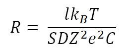
At the intersection of two straight lines an angle is formed; therefore, we consider the markup by pairing the sides of different angles. The figure below shows the pairing of straight, sharp and obtuse angles. Interfaces of the sides of angles a - right; b - acute; in - stupid. The construction is reduced to finding the center of the arc, which would touch both sides of the angle. Let the radius R of the arc (conjugation) of a circle be 40 ...
A perpendicular (figure below) is a straight line that makes a right angle with another straight line or plane. Perpendiculars to the straight line (a) and plane (b) When tapping a thread in the hole, the tap is placed perpendicular to the surface of the part (figure below). The perpendicularity of the tap to the cut hole of the part. Before drilling deep holes in the parts, you must check the perpendicularity of the drill set in the…
With a student protractor you already worked. Using it, you can build any angle. Recall the construction of an angle of 45 °, which is often found when marking: Building an angle of 45 ° using a protractor On a prepared surface of the workpiece, a direct risk of AB is carried out. A point is marked on this risk and a O mark is placed with a center punch. A protractor is applied to the risk so that its starting point ... The markup is done slowly, neatly on a marker plate. The workplace of the planter should be well lit. Before marking study (read) the drawing and determine the main dimensions of the part (length, width, height). The workpiece must have an allowance for processing. Check the workpiece for machinability trial sawing, cutting or bending. The billet must be clean, free from burrs and nodules (if it is ... Sharpening tools TO category: Sharpening tools Sharpening tools Sharpening chisels. The tool is mounted on the sharpening tool of the sharpening machine and, gently pressing on it, slowly and smoothly move across the entire width of the sharpening wheel. During operation, the chisel should be turned over and sharpen one or the other side, periodically cooling the cutting part in water. The cutting edge of the chisel after sharpening should have the same width and inclination to the axis on both sides of the tool. Only in this case the chisel will be sharpened correctly. For cutting iron and bronze, the angle of sharpening, or sharpening, chisels make 70 °, for steel of medium hardness - 60 °, copper and brass - 45 °, aluminum and zinc - 35 °. The tapering angle is checked against a template, which is a plate with angular cuts in 70 °, 60 °, 45 °, 35 ° (Fig. 2).
Fig. 1. Sharpening chisels
Fig. 2. Template (a) and checking the chisel angle (b)
Fig. 3. Grinding scriber After sharpening, the cutting edge of the chisel is filled on an abrasive bar, that is, it is removed from its irregularities. Sharpening scriber. First check the installation manual. If it is located correctly, that is, the gap between it and the abrasive wheel does not exceed 2-3 mm, you can get to work. They turn on the electric sharpener, take a scriber with both hands and, leaning on the handpiece with their left hand, press the working part of the tool to the side surface of the grinding wheel at a small angle to it (Fig. 2). To scribe was sharpened smoothly and correctly, it must always rotate around its axis. Sharpening center punch. After adjusting the gap between the handpiece and the grinding wheel, take the center punch with both hands and, placing the left hand on the punch, set the center punch at an angle of 30-40 ° to the working surface of the circle (Fig. 3). Turning on the electric, they press the working part of the center punch to it and sharpen the tool, turning it around its axis. Using sharpening, the working part of the cutting tool is restored, i.e., the optimum shape, dimensions and roughness of its cutting edges are obtained. Repeated operations of sharpening a blunt instrument are called sharpening. Sharpening incisors. Wear on the rear surface is determined by the value, wear on the front surface - the width B and the depth Nl of the hole. Depending on the processing conditions, the wear of the hard alloy can occur only on the front or only on the rear surface or on both surfaces simultaneously.
Fig. 4. Sharpening the tool on the grinding and grinding machine. If the wear of the cutters does not exceed the permissible value, then the allowance for sharpening is 0.6-0.9 mm. Sharpening incisors produced on grinding and grinding machines (sharpeners), universal sharpening machines and special cutting machines. Installing the cutter on the sharpening handpieces when grinding the front surface is shown in Fig. 4, a; when sharpening the main back surface - in fig. 4, b. When calculating take into account whether a positive or negative angle I and substitute it in the formula, respectively, with a plus or minus sign. The sequence of operations of sharpening and finishing carbide cutter:
Fig. 5. The calculation scheme of the installation angles of the cutter when sharpening in a three-rotary vise on a universal sharpening machine |


Popular:
New
- Markup definition. Planar marking. Types of markup. Questions for self-test
- Pipe bending machines Various variations of pipe bending machine
- Safety during filing
- What should be the sharpening angle of the scriber
- Drawing on preparation of contours of future product
- Modern ways of cutting metal and its defects
- Kerner - so that the drill does not slip off!
- Objects of inanimate nature Examples of the influence of inanimate nature factors on plants
- Finishing joinery
- Block breakdown in AutoCAD - simple and effective teams from practitioners