Site sections
Editor's Choice:
- Expansion joints in buildings
- Chaber - what is it and its purpose
- Sharpening wood cutters: manual work, using grinding wheels and a grinding machine
- Belts and sandriks, crackers and volutes - secret codes of architecture on the example of the old Saratov Sandriks in architecture
- Surface grit - tooling work
- Maximum load on the balcony slab: how much can a balcony withstand in a panel house?
- Projects: symbols on drawings for water supply and sewage
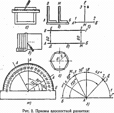
- Marking and marking details How to mark the details with curved contours
- Tools for slotting Tools for slotting
- Tools for chiseling Slotting tools
Advertising
| What to make core. Kerner - so that the drill does not slip off! Which core to choose |
|
There are several ways to mark center holes, but the most widely used are: a) marking using a marking compass (Fig. 105, a) and b) marking using a center-picker fig. 105, d). Before marking, the ends are usually chalked up so that the risks that determine the position of the center holes are more noticeable. Then proceed to markup. Marking with a caliperThe legs of the marking compass (Fig. 105, a) are placed at a distance approximately equal to the radius of the part. A curved leg is applied to the circumference of the butt of the part, clamped in a vice, and an pointed leg draws an arc near the center of the butt. Then, three more arcs are carried out in the same way, each time moving the curved leg of the compass approximately on the circumference of the butt. The drawn four arcs form a curvilinear quadrilateral. If the compass legs are separated by a distance exceeding the radius, then the risks form a figure, as shown in fig. 105, b, and if at a distance less than the radius, then as in fig. 105, c. Figure 105. Marking and naming of the centering hole: a - marking with a marking compass, b and c - marking risks, d - marking with a center-finder, g - centering nosing The center of the hole should be in the center of the resulting quadrilateral. It is marked on the eye and then peg, as shown in fig. 105, d. Center MarkupMarking with the help of a center-finder (Fig. 105, d). Attaching the center-viewer to the end of the part, scribing it at risk, then turning the part or center-searcher about 90 ° and carrying out the second risk. The intersection of the remarks oO determines the position of the center hole. The same is done on the other end. Hole punchingThe centering holes are shown in fig. 105, d. The center punch should be installed vertically, but in no way inclined. In the latter case, when hit with a hammer, the punch will shift from the intended point; in addition, it is possible for the punch to jump off the workpiece and the turner may damage the arm. In details with a diameter of up to 40 mm, it is better to pin the center without marking using a special device called a bell (fig. 106). The device is installed on the end of the part vertically and a hammer on the core of the bell mark the place Instruction card number 1 Topic “Using the marking tool” 1. Purpose and efficiency of the card application The card is intended for organizing the work of students to perform training exercises: Applying scratches using a metal measuring line and scriber. Coreing Using marking compasses. The use of centro searchers. Use of flightmask. Sharpening and refilling marking tools. 2. Equipment, tools and fixtures Metal measuring rulers, scriber, compasses marking single-needle rails, vertical rulers, center-detectors, square-center-detectors, sliding center-detectors, center pins, mechanical centerpieces, hammers with a metalwork 200 g, wooden blocks, a marking plate, sharpening machine , sharpening angle check templates, grinding bars . 3. Instructive instructions
Pic.1 Exercise 1.Scratching with metal measuring rulers and scriber 1.
Attach a ruler to the workpiece. 2. Take a scoop and hold at risk. Scriber to take in his right hand, like a pencil, and, without interrupting the movement, hold the risk of the required length. When carrying out risks, the scriber should be pressed tightly against the ruler, deviating from it by a small angle.
Pic2
Fig. 3 Exercise 2. Coreing 1. Roll a simple tuck at risk. Take the center punch in your left hand with three fingers: thumb, index and ring fingers. Slightly tilting the punch "away", set its edge exactly on risk. Position the center punch perpendicular to the marked plane and apply a gentle blow to the head with a marking hammer. In the same sequence to do the following core cavities (Fig. 2). Observe the following rules for the sintering of marking markings: when threading long scratches (150 mm and more) the distance between the recesses should be 25-30 mm; for short scratches (less than 150 mm), the distance between the recesses should be 10-15 mm; lines of small circles (0 to 15 mm) to be threaded at four mutually perpendicular points; lines of large circles (0 more than 15 mm) coil evenly in 6-8 places; arcs in mates will be twisted with shorter intervals between grooves than on straight lines; the junction points and the intersections of the scratches are mandatory. 2. Screw on the spring with a center punch. Take the center punch in the right hand. Slightly tilting the punch "away", set its edge exactly on risk. Having set the center punch vertically, push it down (fig. 3),
Fig. four
Fig. five Exercise 3. Using marking compass 1. Set the compass legs to size. Take the marking compass in your left hand and slightly release the clamping screw. Set one leg of the compass point on the tenth division of the ruler, and the second - on the division greater than the specified by 10 mm. Fasten the clamping screw, holding the compass by the leg, into which the clamping screw is screwed. Check the set size on the ruler (Fig. 4). Note. The use of compasses with a weakened joint is prohibited. 2. Draw an arc. Apply two mutually perpendicular risks (axes) on the workpiece. Screw the intersection point of the axes, Set the compass legs to the size of the arc radius. Place the point of one (stationary) leg into the core hole made and, slightly pressing both legs to the surface of the part, with the other (movable) leg draw an arc of a given length on the part. When conducting an arc, the compass should be tilted slightly in the direction of motion (Fig. 5)
Fig. 6
Fig. 7
Fig. eight Exercise 4. Using centro searchers 1. Mark the center with a center punch. Note. A center-pivot center marks the centers only at the ends of the cylindrical parts. Install a center pitch detector on the end of a cylindrical part. Holding the centerfinder in an upright position with your left hand, strike the center punch with a hammer (Fig. 6). 2. Outline the center withusing the center square finder. Note. With the help of the square detector, centers are found only at the ends of the cylindrical parts. Install the square-finder on the end of the part in this way; so that the corner bars touch the part. Holding the square-finder with your left hand, hold a scriber at risk on the end of the part. Rotate the square about 90 ° and hold a second risk, the intersection of which with the first one will give the center of the end face - ABOUT. At the point of intersection of the troughs, make a core cavity (Fig. 7). 3. Find the center of the hole using the sliding center finder. Note. With the help of a sliding center-finder, the centers of the holes are found. Tightly insert a wooden bar with a plate made of white tin into the hole so that the plane of the plate is 4--5 mm below the end plane of the part. Spread the center-finder legs to a size approximately equal to the radius of the hole. While pressing the bent leg of the center-viewer to the inner surface of the hole, make a notch on the plate of four mutually perpendicular positions. Identify the “by eye” center inside the four serif arcs and thread it. Check the accuracy of marking the center of the hole and, if necessary, repeat the marking (Fig. 8).
Fig. 9
Fig. ten Exercise 5. The use of flight 1. Set the needle to the required size. Set rehimes on the razmetochnoy plate, the rod / reymasa positioned vertically 2 - horizontally (fig. 9) Scale up the rack and using a vertical ruler 8, preset it to the required size, then fix it on the rack with a clamping screw 4. Rotating set screw 5 on the basis of flightmas, precisely set the tip of the scriber to the required size. 2. Hold on the details of the risk of flight. Carry out the risk of a smooth continuous movement, pressing the base of the plane to the marking plate The raymasa scriber should be tilted in the direction of movement by 60-70 ° with respect to the plane being marked, while maintaining a constant inclination (Fig. 10).
Fig. eleven
Fig. 12
Fig. 13 Exercise 6. Sharpening and refueling marking tools 1. Sharpen (fill) scriber. Check the size of the gap between the handcuff of the sharpening machine and the periphery of the grinding wheel, and if it exceeds 2-3 mm, make the appropriate adjustment (installation). Lower the protective screen and, by pressing the “Start” button, turn on the machine. Take the scriber in both hands and, resting his left hand on the handkerchief, position the scriber at a slight angle to the end surface of the grinding wheel. Rotate the scriber slightly, sharpen it at a length of 12-15 mm (Fig. 11). 2. Sharpen (fill) center punch. Adjust the gap between the arm and the circle, lower the protective screen and turn on the machine. Take the center punch in both hands and position it at an angle of 50-60 ° to the horizontal axis of the circle. To sharpen the center punch on the periphery of the circle, turning it around the axis. Check the grinding angle with a template, which should be equal to 60-70 ° (Fig. 12). 3. Sharpen and tuck in (to bring) the caliper leg. Bring compass legs together. Turn on the machine. Sharpen the legs of the compass from four sides to a square over a length of 15-20 mm so that the tips of both legs converge into one point. Fill (bring) the compass legs alternately on the bar with longitudinal movements (Fig. 13). Among the plumbing tools, there is one of such useful and simple hand tools as the punch. In this article we will talk in detail about this instrument, consider its purpose and types, and also focus on those details that should be remembered when buying a center punch in the store. Well, let's look at all this right now. What is a center punch and what is it for?As already mentioned, the punch is a hand tool designed for plumbing. So, it is used to mark the central holes (the so-called "cores"), which are necessary for the initial installation of the drill, or another visual mark. Externally, the punch is a metal rod having a circular cross section. One of the ends of the tool is the working part, and it is made in the form of a cone, whose angle at the top is 100-120 °. The process that is performed during the work with this tool is called “coreing”. It consists in blows applied by a hammer from the opposite part of the tool’s tool, the so-called butt pad. The use of this tool helps to avoid several unpleasant things - with its help, the drill slippage from the drilling point is excluded, and the corener helps to more accurately perform the drilling process, etc. You can buy a center punch in almost any store of plumbing and manual equipment. On the counter, it is easy to recognize it by the cylindrical shape, at the beginning of which there is a striker, and at the end is a pointed cone. In the middle part of the tool, there are notches or stripes that help hold it tightly in your hands. To get a mark using a center punch, you need to install it with a tapered end to the mark point, and strike the hammer with a hammer. The material from which the punch is made, as a rule, is a solid tool steel, hardened by thermal means. Note that this tool is often called “core”, but this is an erroneous expression. Types and types of center pinsAs we have said, the punch is a hand tool. However, at the same time, there are also automatic punchs, the so-called “crossbows”. This type of instrument suggests a completely different design and device. Outwardly, such a punch looks like a screwdriver, in the handle of which there is a spring and platoon-trigger mechanisms. These mechanisms make the striker move, and, in fact, leave marks on the metal surface.
The advantage of this type of center punch is the fact that it can be used to apply marks with one hand without using percussion instruments, respectively, without using the other hand. Also, the advantage of this center is the ability to adjust the force of impact. This, in turn, allows you to adjust it in such a way as to leave marks even on the softest or most fragile materials and parts that require increased accuracy and care when processing. And, of course, the automatic punch will significantly increase the speed of marking.
Another type of this tool is the electric punch. Its design provides a solenoid, which draws in the tool's core, and then applies a striking action on the center punch pin. As well as the automatic center punch, it is very easy to use, but its design is already somewhat outdated, therefore it is not so often to meet a tool of this type.
Also, there are centers with special mandrels. They will allow the mechanic to very quickly form a mark at a given distance, for example, from the edge, or, conversely, from the center of the part. In short, such a punch allows you to set labels on surfaces that have any specific features. To buy a center punch in a store, it is enough to pay attention to the material, look at its appearance, and look at the manufacturer. The tool from the known producer, is more preferable, than the center punch without any identification marks or distinctions. Therefore, pay close attention to these details, and then the tool will serve you for a very, very long time. More articles from the section: | ||||||||||
2.12; section 6 |
||||||||||


Center pins | Usability | Execution | Steel group | Taper |
||||||
Notes:
1. By request of the consumer, the angle of sharpening of the center punch is allowed to be equal to 90 °.
2. The rounding radius of the impact end must be at least 40 mm.
(Modified edition, Rev. N 2).
An example of the symbol of the performance punch 1
, from steel of group A, with a diameter of working part = 4.0 mm, with H12.Х1 coating:
Kerner 7843-0039 H12.X1GOST 7213-72
2. TECHNICAL REQUIREMENTS
2.1. Center pins should be made of tool steel groups:
A - alloyed steel grades 7HF and 8HF according to GOST 5950;
B - carbon steel grades U7A and U8A according to GOST 1435.
Note. By request of the consumer it is allowed to produce cores from steel of other grades with mechanical properties in thermally processed condition, not lower than the specified steels.
2.2. The hardness of the working and impact parts of the center punch should be as specified in Table 2.
table 2
Steel group | Hardness |
|
The working part of the center pins on a length of 15-30 mm | Impact part of the center pins on a length of 15-25 mm |
|
З6,5 ... 41,5 |
||
2.1, 2.2. (Modified edition, Rev. N 2).
2.3. The roughness of the working cone of the center punch is 2.5 microns, and the remaining surfaces before coating 20 microns according to GOST 2789.
(Modified edition, Rev. N 1).
2.4. Kerners must have one of the protective and decorative coatings listed in Table 3.
-
Phosphate with oiling
Chem. Phos. prm
Chrome 9 microns thick
Chrome 1 micron thick with a 12 micron nickel underlayer applied electrolytically
Zinc thickness 15 microns chrome
Chem. Phos.
Phosphate with the subsequent coloring of the surfaces of the pivots with nitroglyphthalic enamel NC-132 of various colors according to class IV
Em. NC-132 decomp. color IV
Cadmium 21 microns thick chrome
KD 21.hr
Chrome 1 micron thick with a sublayer of nickel applied by electrolytic method 14 microns thick, and nickel applied in the same manner 7 microns thick
Notes:
1. It is allowed in agreement with the consumer to use other metallic and non-metallic coatings in accordance with GOST 9.306 and GOST 9.032, which are not inferior to those specified in Table 3 for their protective and decorative properties.
2. Kerners produced for sale through a retail distribution network must have protective and decorative coatings of at least 2 groups of operating conditions according to GOST 9.303.
It is allowed in agreement with the consumer for sale through the retail distribution network the use of coatings that correspond to group 1 of operating conditions in accordance with GOST 9.303.
The appearance of the center pins intended for export must conform to the standard pattern approved in the prescribed manner.
It is allowed, in coordination with the consumer, to manufacture pivots with a clarified sharpened part, followed by coating the clarified surfaces with a colorless varnish of the types MS-25, AK-113 or with preservation with a lubricant of the type NG-203 GOST 12328.
2.5. Technical requirements for the quality of punch coatings - according to GOST 9.302 and GOST 9.032.
2.4, 2.5. (Revised Edition, Rev. N 3).
2.6. (Deleted, Rev. N 3).
2.7. The admission of coaxiality of conic and cylindrical surfaces relative to a common axis is 0.25 mm.
(Revised Edition, Rev. N 3).
2.8. The reliability of center pins is determined by the total installed resource of 1000 and 800 cores for cores made of alloyed and carbon steels, and the established trouble-free operating time of 400 and 300 cores for cores made of alloyed and carbon steels.
The failure criterion is the appearance of the riveted areas on the impact part of the center punch, the limiting state criterion is the appearance of a blunt radius on the working section of more than 0.3 mm.
2.9. On the non-rolled belts of the cylindrical part of each center punch should be clearly applied:
trademark of the manufacturer;
diameter of the working part;
steel grade on products from chrome-vanadium steel;
product price (for retail).
On the core and on all the accompanying documentation for the center pins, certified for the state quality mark, there should be an image of the state quality mark in the order established by the USSR Gosstandart.
Marking of the center pins intended for export in accordance with the order of the foreign trade organization.
2.10. Inner packing of cores - VU-1, VU-2, VU-3, VU-7 according to GOST 9.014.
2.11. Each punch intended for retail sale must be wrapped in anti-corrosion paper in accordance with GOST 16295 and packed in individual packaging.
2.12. Other requirements for packaging and labeling of transport and consumer packaging - according to GOST 18088.
2.8-2.12. (Introduced additionally, Change. N 3).
Section 3. (Deleted, Rev. N 3).
4. ACCEPTANCE
4.1. Acceptance rules for center pins are GOST 26810.
4.2. Periodic tests, including reliability tests, should be carried out once every 2 years. Tests subjected to center pits of alloyed and carbon steel of the same size.
, GOST 6465.
5.3. Center punch parameters are controlled by universal measuring instruments with an error of no more than:
a) when measuring linear dimensions - established by GOST 8.051;
b) when measuring angles - 35% of the tolerance;
c) when checking the shape and location of surfaces - no more than 25% of the value of the tolerance for the parameter being checked.
5.4. Performance testing of center pins should be carried out by 25 points of diameter equal to the center pins of the center pins for cores = 2 and 3.2 mm; for the rest, at least 3.2 mm on a strip of hot-rolled steel of grade 35 according to GOST 1050.
5.3, 5.4. (Revised Edition, Rev. N 3).
5.5. The thickness of the strip, the distance from the edge of the strip to the center of the pinned point and between the centers of two adjacent points must not be less than 1.5 times the diameter of the working part of the center punch.
5.6. After testing for working capacity, the working part of the punch should not have spalled places and blunting, and on the impact part - cracks, sprinkled places and riveted areas.
(Revised Edition, Rev. N 3).
5.7. The roughness of the surfaces of the pivots is checked by comparison with the roughness samples according to GOST 9378 or profilometers (profilographs).
5.8. Testing of the center pins for reliability is carried out on test benches under the test conditions specified in subclauses 5.4 and 5.5.
At the same time, the test results are considered to be satisfactory if each of the controlled pivots meets the requirements set forth in clause 2.8.
5.7, 5.8. (Introduced additionally, Change. N 3).
6. TRANSPORTATION AND STORAGE
Transportation and storage - in accordance with GOST 18088.
(Revised Edition, Rev. N 3).
Section 7. (Deleted, Rev. N 3).
Electronic text of the document
prepared by CJSC "Code" and verified by:
official publication
M .: IPK Publishing house of standards, 2003
The handwheel is mounted on an electric torch so that the gap between it and the abrasive (grinding) wheel does not exceed 2 - 3 mm. Turning on the electric sharpener, they take the scriber with both hands and, resting their left hand on the handpiece, rotate the scriber on their axis. Sharpen on the side of the abrasive wheel at a small angle to it. The working part of the scriber is sharpened to a length of 15-20 mm.
 |
Having adjusted the gap between the handcuff and the grinding wheel, take the center punch with both hands and position it at an angle of 30-40 ° to the periphery, and not to the side surface of the circle, as when sharpening a scriber. Turning on the electric torch, turn the center punch around its axis, resting its left hand on the handpiece.
Check the angles of sharpening patterns.
Grinding angles for cast iron, bronze 60 °, for soft metals 45 °.
Sharpen marking compass
Prepare the machine in the same way as when sharpening scriber and kerner. The legs of the compass sharpen on the side surface of the abrasive wheel. Together, the compass legs are sharpened on four sides for a length of 15 to 20 mm so that the tips of both legs converge at one point.
Fill the legs of the compass on the bar.
When working on the elektrotochily need to use a protective screen or glasses.
Questions
- What parts is electric?
- List the rules of safe work on elektrotochili.
- On which surface of the abrasive wheel do scribers sharpen?
- Tell us about the sequence of sharpening center.
- How to sharpen marking compass?
Exercises
- Check the condition of scriber, center pins and refuel them.
- Check if the compass is fixed and prepare it for work.
On the prepared surface of the workpiece scriber using a ruler hold an arbitrary line (at risk) AB.

a - making arcs; b - holding a tangent SH to arcs.
Stepping back from the ends of the AB line by 10–15 mm, a center punch is made on it of two recesses O and O 1. The specified compass solution (in our example, 30 mm) installs the leg into the recess O and draws one arc, and from the recess O 1 another arc.
Regarding both arcs, a ruler carries a scriber at risk for SH, which will be parallel to the previously carried out risk - AB. Parallelism check check line. The distance between the risks at any point should be the same (30 mm).
Questions
- What lines are parallel to each other?
- How to run the risk parallel to the smooth edge of the workpiece, using a ruler and compass, if the distance between the edge and the risk is 40 mm?
- How do they check parallelism?
Exercises
- Spend parallel risks using a ruler and compass at a distance of 20 mm, 40 mm, 65 mm.
- In a rectangle with sides of 60 and 130 mm, draw horizontal and vertical centerlines using a ruler and compass. Determine which lines are parallel.
"Plumbing", IG Spiridonov,
G.P.Bufetov, V.G.Kopelevich

At the intersection of two straight lines an angle is formed; therefore, we consider the markup by pairing the sides of different angles. The figure below shows the pairing of straight, sharp and obtuse angles. Interfaces of the sides of angles a - right; b - acute; in - stupid. The construction is reduced to finding the center of the arc, which would touch both sides of the angle. Let the radius R of the arc (conjugation) of a circle be 40 ...

A perpendicular (figure below) is a straight line that makes a right angle with another straight line or plane. Perpendiculars to the straight line (a) and plane (b) When tapping a thread in the hole, the tap is placed perpendicular to the surface of the part (figure below). The perpendicularity of the tap to the cut hole of the part. Before drilling deep holes in the parts, you must check the perpendicularity of the drill set in the…

With a student protractor you already worked. Using it, you can build any angle. Recall the construction of an angle of 45 °, which is often found when marking: Building an angle of 45 ° using a protractor On a prepared surface of the workpiece, a direct risk of AB is carried out. A point is marked on this risk and a O mark is placed with a center punch. A protractor is applied to the risk so that its starting point ...
The markup is done slowly, neatly on a marker plate. The workplace of the planter should be well lit. Before marking study (read) the drawing and determine the main dimensions of the part (length, width, height). The workpiece must have an allowance for processing. Check the workpiece for machinability trial sawing, cutting or bending. The billet must be clean, free from burrs and nodules (if it is ...
Popular:
New
- Markup definition. Planar marking. Types of markup. Questions for self-test
- Pipe bending machines Various variations of pipe bending machine
- Safety during filing
- What should be the sharpening angle of the scriber
- Drawing on preparation of contours of future product
- Modern ways of cutting metal and its defects
- Kerner - so that the drill does not slip off!
- Objects of inanimate nature Examples of the influence of inanimate nature factors on plants
- Finishing joinery
- Block breakdown in AutoCAD - simple and effective teams from practitioners