Site sections
Editor's Choice:
- Expansion joints in buildings
- Chaber - what is it and its purpose
- Sharpening wood cutters: manual work, using grinding wheels and a grinding machine
- Belts and sandriks, crackers and volutes - secret codes of architecture on the example of the old Saratov Sandriks in architecture
- Surface grit - tooling work
- Maximum load on the balcony slab: how much can a balcony withstand in a panel house?
- Projects: symbols on drawings for water supply and sewage
- Marking and marking details How to mark the details with curved contours
- Tools for slotting Tools for slotting
- Tools for chiseling Slotting tools
Advertising
| Planting seam. Expansion joints in buildings. Expansion joints in concrete floors of industrial buildings |
|
Depending on the destination, expansion joints can be divided into temperature, sedimentary, seismic and shrinkage. In a hot pagoda, when heated, the building expands and lengthens, in winter it shrinks during cooling, these thermal distortions lead to the appearance of cracks. Temperature joints divide the above-ground structure of the building vertically into separate parts, which provides independent horizontal movement of individual parts of the building. In the foundations and other underground elements of the building temperature joints are not satisfied, as they are in the ground, not subject to significant changes in air temperature.
The device temperature joints in the outer walls of buildings: A, B - with dry and normal modes of operation; C, D - with wet and wet modes; 1 - insulation; 2 - plaster; 3 - jointing; 4 - compensator; 5 - antiseptic wooden slats 60x60 mm; 6 - insulation; 7 - vertical joints filled with cement mortar. The distance between the temperature joints is determined depending on the material of the walls and temperature indicators of the construction area. The temperature joints of the external walls must be water- and air-tight and non-freezing, for which they must have insulation and reliable sealing in the form of elastic and durable seals of easily compressible and non-crushable materials (for buildings with dry and normal modes of operation), metal or plastic compensators made of corrosion-resistant materials (for buildings with wet and wet modes). Sedimentary Seam Sedimentary seams are taken into account in cases when different and uneven subsidence of adjacent elements of the structure are assumed. Separate adjacent parts of the building can be different in heights and lengths. In this case, the higher part of the building, which will be harder, will press on the ground with more force than the lower part. Such an uneven deformation of the soil can lead to cracks in the walls and in the foundation of the building. Sedimentary seams dissect vertically all structures of the building, including its underground part - the foundation.
Diagrams of the device for expansion joints in buildings: A - sedimentary; B - temperature sedimentary: 1 - expansion joint; 2 - the underground part (foundation) of the building; 3 - the elevated part of the building; If in one building it is necessary to use expansion joints of different types, they are, where possible, combined in the form of so-called temperature-sedimentary seams. Antiseismic expansion joint Antiseismic seams are arranged in buildings under construction in earthquake-prone areas prone to earthquakes. They divide the entire building into compartments, which in the construction are independent stable volumes. Double walls or double rows of supporting columns are arranged along the lines of antiseismic seams, which are the basis of the supporting structure of each individual compartment and provide their independent draft.
The layout of seismic belts in buildings with stone walls and the design of antiseismic belts of the outer wall: A - facade; B - a section along the wall; B - plan of the outer wall; G, D - the inner part; E is a detail of the plan of the antiseismic belt of the outer wall; 1 - antiseismic belt; 2 - reinforced core in the wall; 3 - wall; 4 - floor panels; 5 - reinforcement cage in the seams between the floor panels; Shrinkable expansion joint Shrinkage expansion joints are made in cast-in-concrete frameworks, since the concrete during hardening decreases in volume due to the evaporation of water. Shrink seams prevent the occurrence of cracks that violate the bearing capacity of the cast-in-concrete frame. After the hardening is completed, the remaining shrinkage expansion joint is completely closed. In brick walls, expansion joints are arranged in a quarter or in a sheet pile. In small-block walls, the adjoining of adjacent areas is carried out end-to-end and is additionally protected from blowing by steel compensators. Expansion joints in brick walls: And - in a brick wall, junction in the sheet pile; B - in a brick wall, adjoining in a quarter; B - with a compensator of roofing steel in the small-block wall; 1, 2 - gasket; 3 - steel compensator; 4 - blocks; In industrial buildings that are large in plan or consist of several volumes with different heights and loads on the base, provide for expansion joints, which, depending on the purpose, are divided into temperature, sedimentary and antiseismic. Temperature seams prevent the formation of traces in the structural elements of buildings from deformations caused by fluctuations in the temperature of external and internal air. Temperature joints (longitudinal and transverse), dissecting vertically all the above-ground structures of the building into separate parts, ensure the independence of their horizontal movements. The foundations and other underground elements of the building are not divided by temperature joints, as they are not deformed to a dangerous value under the influence of temperature. Sedimentary seams provide when unequal and uneven draft of adjacent parts of the building is expected. Such a draft can occur with a significant difference in the heights of adjacent parts (more than 10 m or more than 3 floors), with various loads on the base in size and nature, with heterogeneous base soils under foundations and during extension to existing buildings. Sedimentary seams arrange on the border of adjacent parts of the building, and, unlike temperature, they dismember vertically all the building structures, allowing for independent subsidence of its individual volumes. Sedimentary seams also provide horizontal movements of the dismembered parts, so they can be combined with temperature seams. In this case, they are called temperature-sedimentary. The distance between the temperature joints is determined depending on the constructive solution of the building, the climatic parameters of the construction area and the internal air temperature. In heated buildings with precast reinforced concrete frame (or mixed - reinforced concrete columns and metal or wooden surfaces) this distance is equal to 60-72 m, in unheated buildings or in open structures - 40 m. With a steel frame, temperature joints are arranged: in heated buildings after 150-230 m, in unheated buildings and hot shops - after 120-200 m, in open racks - after 130 m. In wooden structures temperature joints do not provide. In single-storey buildings, the seam, as a rule, does not have an insert (Fig. 7, d), in multi-storey buildings it can be with an insert (Fig. 9, e) and without it (Fig. 9, e). Preference is given to the seams without insertion, as in this case no additional protecting elements are required. Columns on both sides of the weld axis are embedded in a common foundation (Fig. 30, b). Longitudinal joints in buildings with a reinforced concrete frame are arranged on two rows of columns with an insert, the width of which, depending on the type of attachment in adjacent spans, is 500 and 1000 mm (Fig. 8, a). In buildings with an all-metal frame and mixed (reinforced concrete columns and metal trusses), the longitudinal joints should be solved on the same row of columns. Fig. 125. Temperature joints in enclosing structures: Transverse and longitudinal temperature seams in the coating are performed without breaking the roofing carpet (Fig. 125, a, b). Along the seams stack semi-cylindrical compensators made of galvanized steel and fasten them to the cover plate dowels. The compensators are used for laying insulation from semi-rigid mineral wool plates, galvanized steel and a water-insulating carpet, which is reinforced within the seam with additional layers of rolled material and fiberglass on mastic. On pitched covers along the longitudinal seam, two rows of water receiving funnels are provided. If there is a difference in the height of the floor, the temperature joint is combined with it. In this case, to seal the roofing carpet on the floor of the lower span, a brick wall is set up, supported by a steel shield. The steel shield is attached to the consoles from the corners, embedded in the seams between the ends of the cover plates. From above, the seam is covered with a compensator and an apron made of galvanized steel (Fig. 125, c). The wall panels adjoining the temperature joint are attached to the framework columns with the same devices as the row panels (Fig. 125, d). In places of seams with an insert, special additional wall blocks are used. The gap between the edges of the seam, having a width of 20 mm, is filled with tarred tow or elastic material, for example, isolate mastic or poroisol. Sometimes, from the outside, the seam is covered with a compensator made of galvanized steel, which is fixed with nails (or dowels) to the wall panels. Temperature joints in floors on the ground with a concrete or other rigid underlying layer should be provided only in rooms with a long negative temperature during the winter period. The distance between the seams in both directions is equal to 6-8 m. Temperature joints in the floors on the floors of high-rise buildings are arranged at the locations of the main joints. In floors with solid and slab coatings (concrete, cement, metal-cement, asphalt concrete, mosaic, from metal plates), in areas with significant mechanical impacts on both sides of the seam, bordering corners are provided that attach to the underlying layer or to the floor slabs with anchors through 0, 5-0.6 m (Fig. 125,<5); иногда перекрывают шов широкой накладкой из эластичной пластмассы (рис. 125, е). Там, где отсутствуют значительные механические воздействия на пол, уголки не предусматриваются. In xylene wood floors, on both sides of the seam, wooden slats are laid, which are attached to antiseptic jams, embedded in the underlying layer or in floor slabs in 0.5-0.6 m. The width of the seam in the hard underlying layer or in the overlap takes 15-20 mm, and in the clothing of the floor - 6-10 mm. The seams are covered with compensators of galvanized steel and filled with elastic materials or mastics. |
||||||||||||||||||||||||||||||||||||||||||||||||||||||||||||||||||||||||||||||||||||||||||||||||||||||||||||||||||||||||||||||||
 Expansion joints in buildings are suitable for reducing the loads on structural elements in places of predicted deformations that occur during temperature fluctuations, seismic effects, uneven ground subsidence and that can cause dangerous loads.


| The average outdoor temperature of the coldest five days | The distance between the temperature seams, m, when laying | |||
| from ceramic bricks and stones including large-format, natural stones, large blocks of concrete or ceramic bricks | from silicate bricks, concrete stones, large blocks of silicate concrete and silicate bricks | |||
| on solutions of brands | ||||
| 50 or more | 25 or more | 50 or more | 25 or more | |
| Minus 40 ° C and below | 50 | 60 | 35 | 40 |
| "30 ° C | 70 | 90 | 50 | 60 |
| "20 ° C and above | 100 | 120 | 70 | 80 |
| Notes
1 For intermediate values of calculated temperatures, the distance between the temperature welds is allowed to be determined by interpolation. 2 The distances between the temperature-shrinkable seams of large-panel buildings of brick panels are assigned in accordance with. |
||||
9.81 Sedimentary seams in the walls should be provided in all cases where uneven settlement of the base of a building or structure is possible.
9.82 Deformation and sedimentary seams should be designed with a tongue or quarter, filled with elastic pads, excluding the possibility of blowing seams.
9.84 Vertical temperature seams in the front layer of multi-layer outer curtain walls (including the filling of frames) should be assigned by calculation to temperature and humidity effects, insolation and solar radiation from the condition of ensuring the strength and crack resistance of the masonry provided that the requirements specified in Appendix D are met.
Vertical spacing thermal joints and their position should be assigned in the project, taking into account the instructions of Appendix D and the design requirements for the pitch of their location.
The thickness of the seam should be taken not less than 10 mm; in the seam filling it is necessary to provide elastic gaskets and weather-resistant mastics.
Requirements for the device of expansion joints
E.4 Horizontal seams are arranged in load-bearing multi-layer walls with a middle layer of effective insulation - in the facing brick layer, in non-load-bearing walls - throughout the entire thickness of the wall.
Horizontal expansion joints in the inner and outer layers of non-load-bearing multilayer walls should be performed at the level of the supporting structures (between the overlying structure and the upper row of masonry).
E.5 Horizontal seams along the height of the building in facing of bearing multilayer walls with a middle layer of effective thermal insulation are allowed to be arranged as follows:
the first seam - under the overlap of the 2nd floor;
D.6. Vertical thermal expansion joints arranged in the front layer of multi-layer outer walls, separated from the main layer of insulation.
D 7. Recommended maximum vertical spacing thermal joints for straight sections of walls 6 - 7 m. Vertical seams at the corners of the building should be located at a distance of 250 - 500 mm from the corner on one of the sides. When the thickness of the cladding layer is 250 mm, the distance between the seams can be increased.
If necessary, increase the distance between thermal joints it is necessary to carry out calculations of temperature deformations taking into account the design features of the walls, the building structure, its orientation to the cardinal points and climatic conditions.
External walls, and together remove the other building structures, if necessary, and depending on the specifics of the building's solution, climatic and engineering-geological conditions of construction - are dissected expansion joints different types:
- temperature,
- sedimentary
- seismic.
Expansion joint is used to reduce the load on various structural elements in places of possible deformations that occur during seismic events, with temperature fluctuations, uneven ground subsidence, as well as other effects that can cause their own loads, reducing the bearing capacity of the structure.
This is a cut in the building structure, which divides the building into separate blocks, which gives the building some degree of elasticity. For sealing filled with elastic insulating material.
Expansion joints are applied depending on the purpose. These are temperature, antiseismic, sedimentary and shrinkage. Temperature joints divide the building into compartments, from ground level to roof inclusive. It does not affect the foundation, which is below ground level, where it experiences less temperature fluctuations, and therefore does not undergo significant deformations.
Some parts of the building may have different heights. Then the base soils, which are located under different parts of the building, perceive different loads. This can lead to cracks in the walls of the building, as well as in other structures.
Also, uneven ground subsidence of the foundation structure may be affected by differences in the composition and structure of the foundation within the building area of the building. This can cause the appearance of sedimentary cracks even in a building of the same height, with a considerable length.
To avoid dangerous deformations, sedimentary seams are made. They differ in that when the building is cut to its full height, the foundation is also included. Sometimes, if necessary, seams of different types are used. Can be combined in temperature-sedimentary seams.
In buildings under construction in an earthquake prone zone, anti-seismic seams are used. Their peculiarity is that they divide the building into compartments, which in a constructive sense are independent stable volumes.
In the walls, which are built of monolithic concrete of various kinds, shrink seams are made. When concrete hardens, monolithic walls decrease in volume. The seams themselves prevent the occurrence of cracks that reduce the bearing capacity of the walls.
Expansion joint - designed to reduce the load on structural elements in places of possible deformations that occur when air temperature fluctuates, seismic phenomena, uneven precipitation of soil and other effects that can cause dangerous own loads, which reduce the bearing capacity of structures. It represents a kind of cut in the building structure, dividing the building into separate blocks and, thus, giving the building some degree of elasticity. For the purpose of sealing is filled with elastic insulating material.
Depending on the destination, the following expansion joints are used: thermal, sedimentary, antiseismic and shrinkage.
Temperature seams they divide the building into compartments from ground level to roof inclusively, without affecting the foundation, which, being below ground level, experiences temperature fluctuations to a lesser extent and, therefore, is not subjected to significant deformations. The distance between the temperature joints take depending on the material of the walls and the estimated winter temperature of the construction area.
Some parts of the building can be of different heights. In this case, the grounds of the foundation, located directly under the various parts of the building, will take different loads. Uneven deformation of the soil can lead to cracks in the walls and other structures of the building. Another reason for the uneven precipitation of soils of the base of the structure can be differences in the composition and structure of the base within the building area of the building. Then, in buildings of considerable length, even at the same height, sedimentary cracks may appear. In order to avoid the appearance of dangerous deformations in buildings, sedimentary seams are arranged. These joints, unlike temperature joints, cut buildings across their entire height, including foundations.
If in one building it is necessary to use expansion joints of different types, they are, where possible, combined in the form of so-called temperature-sedimentary seams.
Antiseismic seams used in buildings under construction in areas prone to earthquakes. They cut the building into compartments, which in a constructive respect should be independent sustainable volumes. Along the lines of anti-seismic seams have double walls or double rows of supporting struts that are included in the system of the supporting frame of the corresponding compartment.
Shrink seams do in the walls erected from monolithic concrete of various kinds. Monolithic walls during the hardening of concrete are reduced in volume. Shrink seams prevent the occurrence of cracks that reduce the bearing capacity of the walls. In the process of hardening of monolithic walls, the width of the shrink seams increases; at the end of the wall shrinkage, the seams are tightly closed.
For the organization and waterproofing of expansion joints using different materials:
- sealants
- putty
- gidroshponki
Expansion joint - vertical gap filled with an elastic material, dismembering the walls of the building. Its purpose is to prevent the appearance of cracks due to temperature differences and uneven precipitation of the building.
 |
 |
|
Expansion joints in buildings and their exterior walls: |
|
Heat shrinkable seams arrange in order to avoid cracks and distortions in the walls caused by the concentration of forces from the effects of variable air temperatures and shrinkage of materials (masonry, concrete). Such seams cut only the ground part of the building.
In order to avoid the appearance of cracks caused by shrinkage deformations in walls made of monolithic concrete and concrete stones, as well as of uncured silicate bricks (up to three months old), it is recommended to lay constructive reinforcement around the perimeter of the building at the level of window sills and above-window bridges in 2- 4 cm2 per floor.
The seams in the walls associated with metal or reinforced concrete structures, must coincide with the seams in the structures.
Maximum permissible distances (in m) between the temperature joints in the walls of heated buildings
| Estimated winter outdoor temperature (in degrees) | Masonry from baked bricks, ceramics and large blocks of all kinds on brand solutions | Masonry of silicate brick and ordinary concrete stones on the brand solutions | Masonry from natural stones on brand solutions | ||||||
| 100-50 | 25-10 | 4 | 100-50 | 25-10 | 4 | 100-50 | 25-10 | 4 | |
| below - 30 | 50 | 75 | 100 | 25 | 35 | 50 | 32 | 44 | 62 |
| from 21 to - 30 | 60 | 90 | 120 | 30 | 45 | 60 | 38 | 56 | 75 |
| from 11 to - 20 | 80 | 120 | 150 | 40 | 60 | 80 | 50 | 75 | 100 |
| from 10 and up | 100 | 150 | 200 | 50 | 75 | 100 | 62 | 94 | 125 |
The distances indicated in the table are to be reduced: for walls of closed unheated buildings - by 30%, for open stone structures - by 50%
With a change in temperature, reinforced concrete structures are deformed: shortened or lengthened, and due to shrinkage of concrete they are shortened. With an uneven draft of the base in the vertical direction, parts of the structures mutually shift.
 Reinforced concrete structures, as a rule, are statically indefinable systems, in which, with a change in temperature, the development of shrinkable deformations and uneven settlement of foundations, additional efforts arise that can cause the formation of cracks. To reduce this kind of effort in buildings of great length, temperature-shrinkage and sedimentary seams are necessary.
In building coatings and ceilings, the distance between the seams depends on the flexibility of the columns and the compliance of the joints; in monolithic structures this distance should be less than in prefabricated ones. When installing roll supports, thermal stresses can be avoided altogether.
In addition, the distance between the temperature joints depends on the temperature difference; therefore, in heated buildings, these distances are independent of all other factors less.
Temperature-shrinkable seams cut structures from the roof to the foundations, and sedimentary seams completely separate one part of the structure from the other. Temperature-shrinkable seam can be formed by the device of paired columns on a common foundation. Sedimentary seams provide in places of a sharp difference in the height of buildings, adjoining newly erected buildings to old ones when erecting buildings or structures on soils of different composition and in other cases where uneven settlement of foundations is possible.
Sedimentary Stitches also form a device of paired columns, but installed on separate foundations.
 |
 |
|
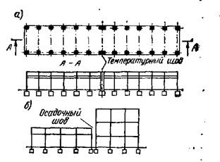
Expansion joints: a - the building is divided by a temperature seam; b - the building is divided by sedimentary seam |
Expansion joints: 1 - temperature weld; 2 - sedimentary seam; 3 - supplementary span of sedimentary seam |
The distances between the temperature-shrinkable joints in concrete and reinforced concrete structures of low structures can be taken constructively, without calculation.
 |
 |
|
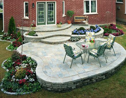
The device of sedimentary (deformation) joints around the perimeter of the building envelope: 1 - entrance group; 2 - decorative blind area; 3 decorative path of outdoor stones; 4 - lawn; 5 - half-closed drainage; 6 - paving of monolithic concrete; 7 - expansion joints with wooden tabs (boards-shorting boards); 8 - the wall of the house; 9 - semi-closed (open) drainage in the form of a tray; 10 - sedimentary (deformation) seam between the base of the house and the base of the entrance group; 11 - windows |
|
|
|
|
|
General view of the construction of a sedimentary (deformation) weld along a 1-1: 1 cut - pebbles (crushed stone, sand); semi-closed drainage (split asbestos-cement pipe) resistant flat stones; 4 - pre-rammed base soil; 5 - sand cushion height from 8 to 15 cm; 6 - a layer of pebbles or rubble 5-10 cm; 7 - short board; 8 - pipe closed bypass drainage; 9 - bedded stone lounger; 10 - basement of the building; 11 - the foundation; 12- rammed base; 13 possible level of groundwater rise; 14 - paving of monolithic concrete End of form |
|

 Sedimentary Stitchesdivide the building lengthwise into parts to prevent the destruction of structures in the event of possible uneven precipitation of individual parts. Sedimentary seams pass from the eaves of the building to the base of the foundation, the location of the seams is indicated in the project. The seams in the walls are made in the form of a tongue, usually 1/2 of a brick, with two layers of roofing; and in the foundations - without a tongue. Above the upper edge of the basement under the tongue of the wall, a gap of 1-2 bricks is left so that during the draft, the tongue does not rest on the laying of the foundation. Otherwise in this place the clutch may collapse. Sedimentary seams in foundations and walls caulk tar tar.
In order to prevent surface water from entering the basement through the sedimentary seam, a clay castle is arranged on its outer side or other measures provided for by the project are applied. Temperature joints protect buildings from cracking during thermal distortions.
Sedimentary seams are arranged in the mating areas of the building:
- located on dissimilar soils;
- attached to existing buildings;
- when the difference in height greater than 10 m;
- in all cases where uneven settlement of the foundation can be expected.
Sedimentary and thermal joints in brick walls should be made in the form of a groove with a groove size for walls 1.5 and 2 bricks thick - 13 x 14 cm, and for thicker walls 13 x 27 cm. In rubble masonry basement walls and foundations the seams can be arranged through.
At the device expansion joints coating roofing carpet is best to break. As a vapor barrier in the construction of an expansion joint, rolled rubber can be used.
 |
 |
|
Expansion joint |
Diagram of the installation of a deformation-sedimentary joint between retaining wall sections |
In cases where the expansion joint is arranged in the watershed areas, and the movement of water flow along the joint is impossible, or the slopes on the roof are more than 15%, then with the device it is permissible to use a simplified design of the expansion joint. The deformation of the building is compensated by the upper mineral wool insulation.
In the roofs with the base of the profiled sheet it is necessary to fix the main layers of the roofing material on the edges expansion joint.
Temperature-expansion jointwith walls of lightweight concrete or piece materials can be installed in roofs with a concrete base or from reinforced concrete plates.
 |
 |
|
Simplified Expansion Joint Design |
Expansion joint in the roof with a base from the profiled sheet |
The wall of the temperature-expansion joint is installed on the supporting structures. The edge of the wall TDSH should be above the surface of the roofing carpet on 300 mm. The seam between the walls must be at least 30 mm.
Metal compensator installed in the temperature-expansion joint, can not serve as a vapor barrier. It is necessary to lay additional layers of vapor barrier material on the compensator.
Temperature joint arrange in the walls of great length in order to avoid the appearance of cracks from temperature changes. Such a seam cuts through the structures of the ground part only, to the foundations, since the foundations being in the ground do not experience temperature effects. The distance between these seams varies from 20 to 200 m and depends on the material of the walls and the area of construction. The smallest joint width is 20 mm.

|

|
| The device of a temperature-expansion joint in the partitions of a building: 1 - masonry of small cellular concrete blocks; 2, 3 - cellular floor slabs; 4 - joint with heat-insulating slab (the presence of fragments of wall material and glue in the joint is unacceptable); 5 - seam in the foundation; 6 - reinforced belt around the perimeter of the building; 7 - reinforced concrete base plate; 8 - reinforced belt around the perimeter of the building with external insulation; 9 - roof with insulation according to the rules of roofing | Vertical expansion joint: 1 - outer facing plates; 2 - hydro windproof layer; 3 - plastering system; 19 - profile for vertical expansion joint; 23 - wooden frame racks; 30 - insulation material |
Sedimentary suture cuts the building to its full height - from the ridge to the foot of the foundation. Such a seam is placed depending on some factors:
when the height difference of the building is not less than 10m;
if the soils that are used as a base have different bearing capacity;
in the construction of a building with a different period of construction.
The smallest joint width is 20 mm
Seismic seam arrange in buildings that are built in seismic areas.

Layout and construction of expansion joints: a - building facade; b - temperature or sedimentary seam with a groove and a ridge; in - a temperature or a sedimentary seam in a quarter; g - temperature joint with compensator; 1 - temperature seam; 2 - sedimentary seam; 3 - wall; 4 - foundation; 5 - insulation; 6 - compensator; 7 - roll insulation.
 Structures of expansion joints should provide the ability to move the ends of the superstructures without overstressing and damage to the elements of the seam, riding clothes, web and spans; must be water- and dirt-proof (exclude ingress of water and dirt on the ends of the beams and supporting platforms); efficient in the set temperature ranges; have reliable anchoring in the span structure; prevent the penetration of moisture on the slab of the carriageway and under the border (to have reliable waterproofing).
Structural material of expansion joints must withstand wear, ular and abrasion, the effects of ice, snow, sand; should be relatively immune to sunlight, oil products, salts.
In the general case, expansion joints should be located:
- between the foundation and wall masonry using bitumen roll materials;
- between warm and cold walls;
- when the wall thickness changes;
- in unreinforced walls longer than 6 m (longitudinal reinforcement of the walls makes it possible to increase the distance between the expansion joints);
- when crossing long bearing walls;
- in places of connection with columns or structures made of other materials;
- in places of sudden changes in wall height.
Sealing expansion joints
Expansion joints are sealed with mineral wool or polyethylene foam. From the side of the room, the seams are sealed with elastic vapor-proof materials, from the outside - with weather-resistant sealants or seals. Facing material should not overlap the expansion joint.
The dimensions of the temperature blocks are taken depending on the type and design of buildings. The greatest distances (m) between the temperature seams in frame buildings that can be allowed without verification calculation.

In addition to temperature deformations, a building may give an uneven draft if it is located on heterogeneous soils or in the case of a sharply differing operational load along the length of the building. In this case, to avoid sedimentary deformations arrange sedimentary seams. In this case, the foundations are made independent, and in the above-ground part of the building, the sedimentary seam is combined with the temperature or with the seam of junction (junction of buildings of different heights, the old building to the new one). Expansion joints arrange in walls and coatings in order to ensure the possibility of mutual displacement of adjacent parts of the building both in horizontal and vertical directions without disturbing the thermal resistance of the seam and its waterproofing properties.
When the device is longitudinal temperature joints or the height difference of parallel spans on paired columns should include paired modular coordination wasps with an insert between them. Depending on the size of the binding columns in each of the adjacent spans, the dimensions of the inserts between the paired coordination axes along the lines of thermal joints in buildings with spans of the same height and with coatings on the truss beams (trusses) are equal to 500, 750, 1000 mm.
 |
 |
|
Binding of columns and walls of one-story buildings to coordinate axes: a - binding of columns to middle axes; b, c - the same, columns and walls to the extreme longitudinal axes; g, d, e - the same, to the transverse axes at the ends of buildings and places of transverse thermal joints; W, W, and - binding columns in the longitudinal temperature joints of buildings with spans of the same height; k, l, m - the same, with a height difference of parallel spans, n, o - the same, with mutually perpendicular junction of spans; p, p, s, t - binding bearing walls to the longitudinal coordinate axes; 1 - columns of high spans; 2 - columns of low spans, which are adjacent to the ends of the increased transverse span |
|
The size of the insert between the longitudinal coordination axes along the line of elevation of parallel spans in buildings with coatings on the truss beams (trusses) must be a multiple of 50 mm:
- bindings to the coordinate axes of the faces of the columns facing the differential;
- the thickness of the wall of panels and a gap of 30 m between its inner plane and the edge of the columns of the increased span;
- a gap of at least 50 mm between the outer plane of the wall and the face of the column of reduced span.
The size of the insert must be at least 300 mm. The dimensions of the inserts at the points of intersection of mutually perpendicular spans (reduced longitudinal to increased transverse) range from 300 to 900 mm. If there is a longitudinal seam between the spans that are adjacent to the perpendicular to the span, this seam is extended to the perpendicular span, where it will be the transverse seam. In this case, the insert between the coordination axes in the longitudinal and transverse seams is equal to 500, 750 and 1000 mm, and each of the paired columns along the transverse seam line must be shifted from the nearest axis by 500 mm. If coating structures are supported on external walls, then the internal plane of the wall is shifted inward from the coordination axis by 150 (130) mm.
Columns to the middle longitudinal and transverse coordination axes of multi-storey buildings are tied so that the geometric axes of the cross section of the columns coincide with the coordination axes, with the exception of the columns along the lines of thermal joints. In the case of binding columns and outer walls of the panels to the extreme longitudinal coordination axes of buildings, the outer face of the columns (depending on the frame design) is shifted outward from the coordination axis by 200 mm or aligned with this axis, and a gap 30 is provided between the inner plane of the wall and the faces of the columns. mm Along the line of transverse thermal joints of buildings with overlappings of precast ribbed or smooth hollow-core slabs, paired coordination axes with an insert between them of 1000 mm in size are provided, and the geometrical axes of paired columns are aligned with the coordination axes.
In the case of extension of multi-storey buildings to single-storey one, coordination axes perpendicular to the extension line and common to both parts of the interlocked building are not mutually intermixed. The dimensions of the insert between the parallel extreme focal axes along the extension line of the buildings are prescribed taking into account the use of typical wall panels - elongated privates or additional ones.
If there are double walls in the joints of the joints, double modular centering axes are used, the distance between which is assumed to be the sum of the distances from each axis to the corresponding wall face with the addition of the size of the seam.
Popular:
New
- Markup definition. Planar marking. Types of markup. Questions for self-test
- Pipe bending machines Various variations of pipe bending machine
- Safety during filing
- What should be the sharpening angle of the scriber
- Drawing on preparation of contours of future product
- Modern ways of cutting metal and its defects
- Kerner - so that the drill does not slip off!
- Objects of inanimate nature Examples of the influence of inanimate nature factors on plants
- Finishing joinery
- Block breakdown in AutoCAD - simple and effective teams from practitioners