Site sections
Editor's Choice:
- Expansion joints in buildings
- Chaber - what is it and its purpose
- Sharpening wood cutters: manual work, using grinding wheels and a grinding machine
- Belts and sandriks, crackers and volutes - secret codes of architecture on the example of the old Saratov Sandriks in architecture
- Surface grit - tooling work
- Maximum load on the balcony slab: how much can a balcony withstand in a panel house?
- Projects: symbols on drawings for water supply and sewage
- Marking and marking details How to mark the details with curved contours
- Tools for slotting Tools for slotting
- Tools for chiseling Slotting tools
Advertising
| Where to grind carbide cutters for metal. Wood sharpening: manual work, using grinding wheels and a grinding machine. Use of equipment for sharpening worm mills |
|
All photos from the article Now manufacturers produce many types and sizes of mills, intended for processing different materials, including wood. You can sharpen a blunt device with your own hands on a universal or special machine, as well as manually.
Features of cuttersDifferent materials are used for the production of cutters. Tool steels are suitable for wood: high-speed, alloyed and carbonaceous. For metal, plastic, ceramics, kamnevidnyh materials used hard alloys, diamonds, elbor, mineral ceramics. Steel for wood cutters
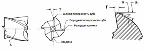
Geometry cloves
According to the design, the cutters of the cutters are divided into sharp (pointed) and ground.
Each tooth is a separate cutter. It has standard parameters: rear (a) and front (y) angles, surface of the surface to be ground (n), angle of inclination (l).
The angle depends on the type of cutter, the brand of its material and the type of workpiece being processed. When cutting wood, the main sharpening angle is selected in the range of 10-20 degrees, sometimes more. The back angle also fluctuates over a wide range of values. Sharpening methods for “wooden” end millsEnd shaped tools for wood can be sharpened manually using a thin diamond bar. The cost of performing this operation by a specialist is also low. Manual work
Changing the position of the needle-copier so that its end touches various points of the tooth groove (for example, center, edge), you can change the values of the rear corners a and a1. Now about the sharpening of the end cutters.
ConclusionSharpening is quite a complicated operation. Relates to the process should be very careful. After all, further efficiency with wooden blanks depends on it. The video in this article will continue to acquaint you with the sharpening nuances. How to sharpen the cutter for metal 11.09.2017 21:16 The industry produces a huge amount of cutters for metal and their sharpening is often a problem for those who work with them. The design features of the tool and a large number of teeth causes difficulties with sharpening. How correctly to grind a mill on metal?As a rule, sharpening cutters for metal produced on special equipment. Improper sharpening leads to breaking of the teeth and failure of the cutter. Proper sharpening of the milling cutter allows you to use the tool for much longer time and reduce wear. Also for this purpose it is necessary to closely monitor the cutting surface of the teeth of the cutter. For sharpening metal cutters, special machines and special equipment are used. Therefore, it is better to entrust this business to professionals. The peculiarity of sharpening mills is the relatively large extent and curvature of the cutting edges of their teeth. When sharpening is required to ensure the movement of the surface of the circle exactly along the edge. What are the cutters
In the metalworking industry, the use of cutters as a cutting tool is widespread. Virtually all parts of various engines, both electric and internal combustion, are manufactured using milling. Many parts for household appliances, machine tools and accessories are also processed using cutters. Request a call back: We produce sharpening:
Properly performed sharpening tool reduces its consumption and, accordingly, increases its resource. Therefore, it is necessary to closely monitor the state of the cutting edges and to produce timely sharpening of the tool, avoiding excessively large wear and especially its breakage. Sharpening and making worm milling cuttersThe production complex of the Spetsstanmash plant offers a full range of services for the manufacture and repair of metal parts and structures, including: the production and sharpening of cutters for metal, wood, cast iron, aluminum, graphite or plastic. The milling cutter is an important tool in industry and workshops. Represents a detail of different form, with a distinctive feature of sharp teeth. Its main function is the machining of the harvested material. The principle of milling is the translational rotational movement of the cutter teeth. Depending on the type of tool used, the result is:
An important characteristic of the cutter is the material of its manufacture, in particular the cutting part. It can be teeth of high-speed steel, mineral ceramic, metal ceramics or diamond. Diamond cutters are considered to be the most durable due to their natural physical characteristics. But, they are the most expensive. All other materials become dull after some time during operation, especially if the operation is incorrect. Buying new tools is expensive, but our skilled craftsmen and high-precision modern equipment allow the quality to perform this type of repair, like sharpening knives for any geometry cutter:
Professional work on grinding cutters increases the resistance of the part, and significantly reduces the consumption of cutting teeth. Sharpening worm cutters: from 600 rub. / PC. (depending on wear) Devices for sharpening the end cutting elements of the milling-chipping machine, are divided according to the nature of work and are divided into two types - universal and special. Below we consider each of these options. 1 Machines for sharpening cutters for metal - an overview of factory modelsSharpening mills for work on metal and wood is done by hand with the help of worm universal devices. In addition, the cutting elements of the milling machine can be sharpened with the help of special tools. Both homemade and universal machine for sharpening end mills on wood is equipped with devices that provide fastening, installation and sharpening details. When choosing the presented tool for sharpening knives of the milling-canting machine with your own hands, it is necessary to consider such parameters as:
The most appropriate device for sharpening the end knives of milling-canting equipment is Kaindl KSS. This small unit is capable of producing professional sharpening end-blades quickly and efficiently. Such a device is several times cheaper than professional equipment and is easy to use. Kaindl KCC is used to adjust the cutting edge of diamond circular saws and cutters, and is also ideal for home use. Presented equipment for sharpening drills, end knives, diamond circular saws.
Effective sharpening of the cutters of the worm milling units is carried out thanks to the precise fixation of the tool in any position. Prisms and thrust pins are used for this. The grinding disc itself can be configured to work in any position using a special hinged holder. The main feature of such a machine is the use of a conventional drill instead of an electric motor. The universal hinge fastening system allows you to connect any type of drill to the device. Sharpening knives milling machines can be made using the device brand Ruko, which is equipped with a laser regulator. This equipment can work with cutting edges with a diameter of 12 to 100 mm. The presented device is quickly and easily installed with your own hands, this is facilitated by a special stepping holder.
Before installing the cutting edges of the worm milling aggregates, a laser pointer can be used for precise positioning. The sharpening angle changes smoothly (stepless). The process itself takes place with the use of diamond disks with a diameter of 125 mm, and for more correct processing you can attach a magnifying glass equipped with neon lights. 2 Making a machine for sharpening your own hands.For the manufacture of a device for sharpening the blade of the milling canter, you will need an electric motor with a capacity of not more than 1 kW, two pulleys and bearings with a shaft. Homemade machine need to start collecting from the bed. The bed is made using steel corners. In addition, a homemade machine must be equipped with a handhold. To install it, a turntable is constructed.
This design will help in adjusting the inclination of the cutting part of the milling-chipping machine towards the grinding wheel. Sharpening of the cutters is performed in such a way that the installed cutting part can minimally touch the rotating wheel. When working, it must be slowly brought to the disk. The self-made sharpening machine can be made according to a predetermined pattern. This takes into account the location of the grinding wheel relative to the handpiece. A homemade machine for sharpening knives of milling-canning equipment must be equipped with a protective casing, which will cover the playing circle. When assembling it should be noted that the gap between the installed plate and the wheel making the grinding should not exceed 3 mm. Homemade mini sharpening machine the cutters of the milling-chipping unit must be equipped with flanges that will provide clamping. It is worth considering, the length of the flanges should not be less than a fourth of the diameter of the grinding wheel. When self-assembling in the gap between the nut and the flange need to put paronitovuyu gasket. Thanks to her, the nut is as tight as possible on the gross section. 2.1 How to sharpen the cutter with your own hands?The sharpening of the knife milling-chipping unit can be carried out without the presence of special mechanisms and devices. To do this, you can use a diamond bar, which is placed on the edge of the workbench or desktop. Sharpening the edge of the knife is made by holding on its front surface with a bar. Pre-cutting element must be cleaned of dirt and dust with a solvent. If the cutter is equipped with a guide bearing, it must be removed before grinding. If this is not done, then the cutter is likely to be deformed. When sharpening, the bar periodically needs to be wetted with a small amount of water, and after the work is finished, wipe it dry. It is important to know that in the process of grinding the front surface the edge of the blade will be sharp, and its diameter will decrease slightly. In addition, when sharpening knives of a milling-worm machine in order to maintain the symmetry of the edge, you need to repeatedly produce movement, ensuring uniform pressure. Depending on the material from which the mill is made, instead of a bar, you can use abrasive (sandpaper) paper. It is mounted on a strip of steel or wooden rail. You can also correct the blade using a grinding machine that rotates at low speed. The device can be equipped with an appropriate abrasive wheel. 2.2 Proper sharpening cutters (video)2.3 Safety rules when sharpeningWhen carrying out work it is extremely important to adhere to the following safety requirements:
It is important to bear in mind that when installing a handpiece, the gap between it and the circle did not exceed 3 mm. In this case, the pad of the handpiece should be located on the damage of the horizontal axis not higher than 10-15 mm. If the gap exceeds the specified value or the handpiece turns out to be lower than the horizontal axis, it can be torn out and stuck in a circle. In addition, you need to pay attention to the absence of chipping and potholes on a rotating grinding element. It is strictly forbidden to touch in a rotating circle, in order to avoid injury of fingers, you should use leather fingertips or thick-cloth construction gloves. When working, the blade should be tightly pressed against the handhold, it is forbidden to sharpen, keeping it on weight. In the process of adjusting the cutting edge can not bring the tool to the circle quickly. Press it should be gradually moving on the surface of the handhold. In such work, the wheel will grind evenly and can be reused. If the circle is sharply applied to the tool to be sharpened, it will be generated unevenly and will quickly become unusable.
When working with a hardened steel cutter, it is necessary to interrupt the sharpening as often as possible, since from excessive pressing to the rotating surface, the blade may heat up and lose its initial hardness. When installing the tool it should be securely fastened in a vice or sharpening device. If the cutter is poorly fixed, then it can pull out, which would entail damage to the circle. When grinding, it is forbidden to stoop to the tool to observe the process. The very moment when the wheel touches the blade can be determined by the spark that appears. You can determine the degree of sharpening after the tool has been moved to a safe distance. If during operation the machine starts vibrating, it must be immediately turned off and the moving joints checked. By following these simple security rules, you can perform all the necessary manipulations quickly and efficiently. Grinding cutters - the final operation to obtain the specified geometrical parameters, as well as to restore the cutting properties lost as a result of wear of the teeth. Properly performed sharpening increases the resistance of the cutter, and therefore reduces the consumption of the cutting tool. During operation, the cutters should not be brought to wear values exceeding the established optimal values taken as a criterion for dulling. Therefore, it is necessary to monitor the state of the cutting edges and make timely grinding of the cutters, avoiding excessive wear and breakage of the teeth. Grinding of mills is made on universal-grinding machines, for example, model ZA64 or on special grinding machines. To ensure the correct sharpening of the cutters, compliance with the established standards for permissible beatings, ensuring the established quality of the surfaces and cutting edges, it is necessary that the sharpening machines and devices meet the following requirements:
The correct choice of the grinding wheel and sharpening modes allows you to get the specified geometrical parameters of the cutting part and the required quality of the sharpened surface, which is associated with an increase in the cutting properties of the cutter. Sharpening mills from high-speed steels, increased productivity - cobalt and vanadium - is significantly different from sharpening mills from high-speed steel R18. These steels are characterized by poor grinding and increased tendency to burns. Sharpening cylindrical cutters with pointed teethSharpening a tool with a helical tooth, including cylindrical mills, is carried out on universal sharpening machines. Cylindrical cutters with pointed teeth are sharpened on the back surface with cup and disk circles (Fig. 206). When sharpening cutter worn on the mandrel. The axis of the cup circle is set relative to the cutter so that the circle touches the ground cutter with only one side. To this end, the end plane of the cup circle is inclined at an angle of 1-2 ° to the axis of the cutter (Fig. 206, a). For the formation of the back angle, the axis of the cup circle is located below the axis of the mill to be sharpened by the value H (Fig. 206, b), which is determined depending on the diameter of the mill and the back angle. Fig. 206. Scheme sharpening cylindrical cutter with pointed teeth If the axes of the cup circle and the cutter are in the same horizontal plane, then the back angle and after sharpening will be zero (Fig. 206, c). The position of the cutter tooth during grinding is fixed by the stop, which is installed very close to the cutting edge. Sometimes a special device is used to set the stop in height. When grinding cylindrical cutters with disc circles, the posterior surface of the tooth gets a somewhat concave shape with an increased value of the posterior angle. However, with the right choice of the diameter of the grinding wheel, this concavity does not have any harmful effect. Face grindingFace mills made of high-speed steel, as well as a number of milling cutters equipped with carbide plates are sharpened assembled. Sharpening of the main back surface of face milling cutters is performed by the face plane of the cup grinding wheel (Fig. 207, a). When sharpening the auxiliary rear surface (Fig. 207, b), the cutter is first set so that its auxiliary cutting edge is horizontal. Then the axis of the cutter is rotated in the horizontal plane by the amount of the auxiliary angle in the plan φ 1 and at the same time it is tilted in the vertical plane to the end clearance angle α 1.
Fig. 207. Sharpening face milling Sharpening the front surface of the tooth of the cutter is made as the end face of the grinding disc, and the periphery of the disk. When sharpening, it is necessary to form the angles φ, γ and λ specified in the drawing. Sharpening end millsSharpening of end mills with a screw tooth is also carried out manually on universal sharpening machines. Sharpening of end mills on the main rear surface is performed in the same way as cylindrical mills with the end surface of the cup circle, when the end mills are installed in the centers. The sharpening on the auxiliary back surface is carried out like a face cup. Currently, a semi-automatic model B3125 is produced for sharpening end mills with a diameter of 14-50 mm on the front and rear surfaces. Sharpening disc millsSharpening disk cutters on the main back surface is made like sharpening cylindrical and end mills with a cup wheel. Sharpening on the auxiliary rear surface of the end teeth is done in the same way as for the end mills. When sharpening the front teeth on the front surface, the teeth that are sharpened are directed upwards, and the mills are upright when the milling cutter has simple teeth and are inclined - when sharpening the milling cutters with multidirectional teeth. The angle of inclination of the axis of the cutter in the vertical plane is equal to the angle of inclination of the main cutting edge. Grinding sharpened teethShaped cutters with a ground tooth sharpen only on the front surface. The value of the front angle and after sharpening should deviate from the specified value by no more than ± 1 °, since a change in the front angle causes distortion of the shaped profile. Cutters with straight grooves are sharpened with the flat side of the cup circle (Fig. 208, a), and cutters with screw grooves with its conical side (Fig. 208, b).
Fig. 208. Sharpening the front surface of shaped cutters So that after sharpening the cutting edges have a minimum beating, it is recommended to sharpen using a copier having the same number of teeth as the mill being sharpened (fig. 209). The wear of ground cutters on the back surface is allowed no more than 0.5-0.75 mm. With a larger amount of wear the cutter should be sharpened throughout the profile, which significantly increases the cost of sharpening.
Fig. 209. Sharpening the front surface of the milling cutter with teeth on the copier Sharpening of milling cutters (milling heads)Individual sharpening of set cutter cutters can be made only on a sharpener with a handcuff or on a universal grinding machine with a cutter mounted in a three-turn vice. When fixing the incisors in a vice, in order to avoid the formation of cracks in the lamellae, it is recommended to use a foam rubber strip between the movable vise sponge and the inserted tooth as a shock absorber. Each plug cutter face mill sharpen completely with a single installation. With this method of grinding grinding wheel wear does not affect the accuracy of grinding. Rotation of the circle when sharpening carbide plate should be directed from the base to the cutter blade to avoid microchipping during the sharpening process. In industry, face mills are used, the knives of which are sharpened in the assembly. Face mills from a composite are ground by diamond circles АСО 8-10 Б1 100% on the equipment used for sharpening carbide mills. Milling cuttersThe finishing of the working edges of the cutter is primarily carried out in order to ensure the specified requirements for surface roughness. In addition, fine-tuning allows in some cases to eliminate thin surface layers with burns and cracks that have arisen during sharpening, and other defects of the surface to be brought. The most widespread diamond and abrasive finishing. The carbide tooling is carried out with diamond circles on a bakelite bond, abrasive finishing with fine-grained circles of green silicon carbide. Finishing is mainly subjected to tools equipped with plates of hard alloys and mineral ceramics on special finishing machines. So, for example, diamond finishing by the ribbon of multifaceted non-reversible plates is carried out on a special finishing machine of the model ZV-20 in special cassettes; debugging of the reference plane should be done on a surface grinding machine in special cassettes with diamond discs. The finishing of carbide tools with diamond discs ensures the surface quality of a higher grade of roughness compared to sharpening circles from green silicon carbide and finishing with boron carbide. When milling plastic materials with low strength and a strong abrasive action, diamond finishing allows to increase the resistance by two to five times compared with only sharpening circles of green silicon carbide. This difference with increasing cutting speed increases. When milling high-strength, hard steel and titanium alloys, especially at lower cutting speeds and when using brittle hard alloys, finishing with diamond circles is either ineffective or leads to a decrease in tool life due to chipping of the cutting edges of the cutters. The use of diamond wheels such as APV, APVD, AFC, AT, A1T, etc. when sharpening and finishing a carbide tool with abrasive wheels can improve processing performance 1.5-2 times and get high quality surface finish (roughness R a = 0.32 -0.1 microns). The use of composite wheels (Elbor) when sharpening cutting tools from high-speed steels in comparison with conventional abrasive wheels also has a number of advantages. Milling control after sharpeningWhen checking the cutters after sharpening, check the geometrical parameters of the cutting part of the cutter, the beating of the cutter and the roughness class of the sharpened or finished surfaces. To control the geometrical parameters of the cutters used a number of devices. The main requirement for these devices is ease of operation and the ability to use them directly at the workplace. In fig. 210 shows diagrams of measuring the front and rear corners of the cutter using a protractor.
Fig. 210. Schemes for measuring geometrical parameters of cutters The protractor consists of an arc 1 with a scale divided by risks corresponding to the number of teeth of the measured milling cutter. Sector 2 moves along arc 1 and is fixed in position with screw 3. Sector is equipped with degree scales, on which angles are measured: front angles - on a scale v and rear angles - on a scale a. Sector 2 is attached to sector 2. The rake angle, as mentioned above, is measured in a plane perpendicular to the main cutting edge of the mill. Therefore, when measuring, the reference bar 4 of the protractor is positioned in this plane (the main section plane). In the process of measuring the rake angle (Fig. 210, a), the protractor is placed on two adjacent teeth of the mill, and on one and i teeth the protractor is supported by the gauge 4 along the cutting edge of the mill, and on the other tooth on the front surface of the tooth with its measuring ruler 1 The ruler 1 in the groove is set in height in accordance with the size of the straight section on the front surface of the tooth. Sector 2 of the protractor is rotated until the vertical face of the measuring ruler 1 (knife side) is aligned with the front face and in this position is fixed with the screw 3. The correct installation of the measuring range 1 relative to the front surface is determined by the lumen. When properly installed, there should be no gap between them. The counting is performed on the right side of the sector with the inscription "front angle" against the stroke with a mark corresponding to the number of teeth of this cutter (for example, 6, 8, 10, etc.). In fig. 210, and it can be seen that if, for example, z = 8, then v = 10 °, etc. The back angle of the cutter is measured in a plane perpendicular to the axis of the cutter. In this regard, the support surface of the ruler 4 of the protractor should also be located in these planes. The support ruler 4 goniometer rests in the cutting edge of the cutter's tooth, and the other tooth - on the back surface of the horizontal edge of the measuring range 1. Sector 2 of the goniometer rotates to the “gapless” alignment of the back surface with the measuring edge of the ruler, also defined on the lumen. Counting in this case is performed on the left side of the sector with the inscription "back angle" also against the stroke with a mark corresponding to the number of teeth of the cutter. In the case shown in fig. 210, b, at z = 8, a = 27 °. The error of the protractor is approximately 1 ° 30 ". Teeth beat control Cutters are made using the indicator in those devices where they are sharpened in center heads or in special devices. Cutters, in which the seat is the hole, with the control set on a horizontal or vertical mandrel. Cutters with a cylindrical or tapered shank in the control set either in the guide prism or in the device to control the beat of the working part of the end tools. The beating is checked on the cylindrical surface of the teeth, on the end teeth, on the angular edges and on the supporting end. Check the beat of the cutter produced after installing it on the mandrel or on the spindle of the milling machine. Check the quality of sharpening or finishing produced by an external inspection with a magnifying glass. Cutting edges of the cutters should be sharp, without chipping and potholes. The presence of cracks on the carbide plates is determined using a magnifying glass, wetting the plates with kerosene or sandblasting them. In this case, if there are cracks, kerosene acts. test questions
|


Popular:
New
- Markup definition. Planar marking. Types of markup. Questions for self-test
- Pipe bending machines Various variations of pipe bending machine
- Safety during filing
- What should be the sharpening angle of the scriber
- Drawing on preparation of contours of future product
- Modern ways of cutting metal and its defects
- Kerner - so that the drill does not slip off!
- Objects of inanimate nature Examples of the influence of inanimate nature factors on plants
- Finishing joinery
- Block breakdown in AutoCAD - simple and effective teams from practitioners