Site sections
Editor's Choice:
- Expansion joints in buildings
- Chaber - what is it and its purpose
- Sharpening wood cutters: manual work, using grinding wheels and a grinding machine
- Belts and sandriks, crackers and volutes - secret codes of architecture on the example of the old Saratov Sandriks in architecture
- Surface grit - tooling work
- Maximum load on the balcony slab: how much can a balcony withstand in a panel house?
- Projects: symbols on drawings for water supply and sewage
- Marking and marking details How to mark the details with curved contours
- Tools for slotting Tools for slotting
- Tools for chiseling Slotting tools
Advertising
|
The adhesion and cohesion of concrete, its shrinkage, roughness and porosity of the forming surface of the formwork affect the adhesion of the formwork to concrete. The amount of adhesion can reach several kg / cm 2, which complicates the work on demolding, impairs the surface quality of the concrete product and leads to premature wear of the formwork panels. Concrete adheres to the wooden and steel surfaces of the formwork stronger than to the plastic due to the weak wettability of the latter. Varieties of lubricants: 1) aqueous suspensions of powdered substances that are inert with respect to concrete. When water evaporates from the slurry, a thin layer forms on the surface of the formwork, preventing the adhesion of concrete. most often used suspension of: CaSO 4 × 0.5H 2 O 0.6 ... 0.9 weight. hours, lime paste 0.4 ... 0.6 parts by weight, LST 0.8 ... 1.2 parts by weight, water 4 ... 6 parts by weight These lubricants are erased with a concrete mix, pollute concrete surfaces, and therefore are rarely used; 2) hydrophobic lubricants are most common on the basis of mineral oils, emulsol or salts of fatty acids (soap). After their application, a hydrophobic film is formed from a number of oriented molecules, which degrades the adhesion of the formwork to the concrete. Their disadvantage: concrete surface contamination, high cost and fire hazard; 3) lubricants - retarders of concrete setting in thin butt layers. Molasses, tannin, etc. Their disadvantage is the difficulty of regulating the thickness of the concrete layer, in which setting slows down. 4) combined - the properties of the forming formwork surfaces are used in combination with the slowing down of the setting of concrete in the butt layers. Preparing them in the form of inverse emulsions, in addition to water-repellent agents and retarders, plasticizing agents can be added: LST, mylonaph et al., Which reduce the surface porosity of concrete in the butt layers. These lubricants do not exfoliate for 7–10 days, they are well kept on vertical surfaces and do not contaminate concrete. Formwork installation . Assembling of form forms from inventory formwork elements, as well as installation of the volume-resettable, sliding, tunnel and rolling forms in the working position should be made in accordance with the technological rules for their assembly. Forming formwork surfaces must be bonded with anti-adhesive lubricant. When installing structures supporting formwork, the following requirements are met: 1) racks should be installed on the bases with a bearing area sufficient to protect the concrete structure from unacceptable subsidence; 2) yarns, ties and other fastening elements should not interfere with concreting; 3) fastening of strands and braces to previously concreted reinforced concrete structures should be made taking into account the strength of the concrete by the time the loads are transferred to it from these fasteners; 4) the base for the formwork must be verified before it is installed. Formwork and spinning reinforced concrete arches and vaults, as well as formwork of reinforced concrete beams with a span of more than 4 m should be installed with a construction lift. The amount of construction elevation must be at least 5 mm per 1 m of span of arches and vaults, and for beam structures - at least 3 mm per 1 m of span. To install the formwork beams on the upper end of the rack wear sliding clamp. On the posts on fork supports, mounted on the upper end of the rack, install the girders, on which the formwork boards are installed. Sliding girders also support the girders. They can also be supported directly on the walls, but in this case, supporting sockets should be made in the walls. Before installing collapsible formwork, expose beacons, which are painted with red paint, which fix the position of the working plane of the formwork panels and supporting elements. Elements of the formwork, supporting scaffolding and scaffolding should be stored as close as possible to the workplace in stacks of no more than 1 ... 1.2 m by make so as to ensure free access to any element. Raise shields, poles, pillars, and other elements, as well as bring them to the workplace on the scaffolding in the packages with lifting mechanisms, and fasteners should be supplied and stored in special containers. The formwork is assembled by a specialized link, accepted by the master. It is advisable to mount and dismantle the formwork with large-sized panels and blocks with maximum use of mechanization tools. The assembly is carried out on hard-surface installation sites. The panel and the unit is installed in a strictly vertical position with screw jacks installed on the struts. After installation, if necessary, install the ties, fastened with a wedge lock on the contractions. Formwork for structures more than 4 m in height is collected in several tiers in height. The panels of the upper tiers are supported on the downstream or mounted on the support brackets installed in the concrete, after dismantling the formwork of the lower tiers. When assembling the curved shape forms, special tubular contractions are used. After the formwork is assembled, it is straightened by tamping the wedges successively in diametrically opposite directions. test questions 1. What is the main purpose of formwork for monolithic concreting? 2. What types of formwork do you know? 3. What materials can formwork be made of? 13. Reinforcement of reinforced concrete structures General information. Steel reinforcement for reinforced concrete structures is the most widespread type of high-strength rolled products with temporary resistance from 525 to 1900 MPa. Over the past 20 years, the world production of rebar has increased about 3 times and reached more than 90 million tons per year, which is about 10% of the total output of rolled steel. In 2005, 78 million m 3 of concrete and reinforced concrete were produced in Russia, the volume of steel reinforcement use was about 4 million tons, at the same pace of construction development and a full transition in conventional reinforced concrete to reinforcement classes A500 and B500 in our country in 2010 consumption of about 4.7 million tons of reinforcing steel is expected on 93.6 million m 3 of concrete and reinforced concrete. The average consumption of reinforcing steel per 1 m 3 of reinforced concrete in different countries of the world is within 40 ... 65 kg, for reinforced concrete structures manufactured in the USSR, the average consumption of reinforcing steel was 62.5 kg / m 3. Savings due to the transition to A500C steel instead of A400 is expected to be about 23%, and the reliability of reinforced concrete structures is enhanced by eliminating the brittle fracture of reinforcement and welded joints. In the manufacture of precast and monolithic reinforced concrete structures, rolled steel is used for the manufacture of reinforcement, embedded parts for the assembly of individual elements, as well as for assembly and other devices. Steel consumption in the manufacture of reinforced concrete structures is about 40% of the total metal used in construction. The share of core reinforcement is 79, 7% of the total volume, including: ordinary reinforcement - 24.7%, increased strength - 47.8%, high-strength - 7.2%; wire reinforcement share - 15.9%, including ordinary wire 10.1%, increased strength - 1.5%, hot rolled - 1%, high-strength - 3.3%, the share of rolled products for embedded parts is 4.4%. The armature installed according to the calculation for the perception of stresses in the process of manufacture, transportation, installation and operation of the structure is called working, and installed for structural and technological reasons is assembly. Working and assembly valves are most often combined into reinforcement products — welded or knitted nets and frames, which are placed in the formwork strictly in the design position in accordance with the nature of the reinforced concrete structure under load. One of the main tasks solved in the production of reinforced concrete structures is to reduce the consumption of steel, which is achieved by using reinforced reinforcement. New types of reinforcing steels are being introduced for conventional and prestressed reinforced concrete structures that displace inefficient steels. For the manufacture of reinforcement, low-carbon, low or medium-alloyed open-hearth and converter steels of various grades and structures, and, consequently, physical and mechanical properties with diameters from 2.5 to 90 mm, are used. The reinforcement of reinforced concrete structures is classified according to 4 features: - According to the manufacturing technology, there are hot rolled rod steel supplied in rods or coils depending on the diameter and cold-drawn (made by drawing) wire. - According to the method of hardening, core reinforcement can be hardened thermally and thermomechanically or in a cold state. - The shape of the surface of the reinforcement can be smooth, periodic profile (with longitudinal and transverse edges) or corrugated (with elliptical dents). - According to the method of application, valves are distinguished without pre-tension and with pre-stress. Varieties of reinforcing steel. For the reinforcement of reinforced concrete structures used: rod steel that meets the requirements of the standards: hot rod steel - GOST 5781, the classes of this reinforcement are denoted by the letter A; rod thermomechanically hardened - GOST 10884, classes denoted by At; low-carbon steel wire - GOST 6727, smooth denoted B, corrugated - BP; carbon steel wire for reinforcement of prestressed reinforced concrete structures - GOST 7348, smooth denoted B, corrugated – BP, ropes according to GOST 13840, denoted by the letter K. In the manufacture of reinforced concrete structures it is advisable to save metal to use reinforcing steel with the highest mechanical properties. The type of reinforcing steel is chosen depending on the type of structures, the presence of prestress, the conditions of manufacture, installation and operation. All types of domestic non-stressed reinforcement are well welded, but are produced especially for pre-stressed reinforced concrete structures and types of reinforcement that are restricted to or not welded. Rod hot-rolled fittings. Currently, there are two ways of designating classes of core reinforcement: А-I, А-II, А-III, А-IV, А-V, А-VI and respectively А240, А300, А400 and А500, А600, А800, A1000. In the first way of designation, different reinforcing steel with the same properties may be included in the same class, with an increase in the reinforcing steel class, its strength characteristics increase (conditional elastic limit, conditional yield strength, temporary resistance) and deformability rates (elongation after rupture, relative uniform elongation after rupture, relative narrowing after rupture, etc.). In the second way of designation of rod reinforcement classes, the numerical index indicates the minimum guaranteed value of the conditional yield strength in MPa. Additional indices used to designate core reinforcement: Ac-II - reinforcement of second class, intended for reinforced concrete structures used in the northern regions, A-IIIb - reinforcement of the third class, hardened by exhaust, At-IVK - thermally strengthened reinforcement of the fourth class, with increased resistance to stress corrosion cracking, At-IIIС - III-grade temperature-strengthened reinforcement weldable. Rod fittings are available in diameters ranging from 6 to 80 mm, fittings of classes A-I and A-II with a diameter of up to 12 mm and class A-III with a diameter of up to 10 mm, inclusive, can be supplied in bars or coils, the rest of the fittings are supplied only in bars from 6 to 12 m, measured or unmeasured length. The curvature of the rods should not exceed 0.6% of the measured length. Steel class A-I is made smooth, the rest is a periodic profile: class A-II reinforcement has two longitudinal ribs and transverse projections running along a three-way helix. When the diameter of the reinforcement is 6 mm, protrusions are allowed along the one-way helix, and with a diameter of 8 mm - over the two-way helix. Armature class A-III and above also has two longitudinal ribs and transverse protrusions in the form of "Christmas tree". On the surface of the profile, including the surface of the ribs and protrusions, there should be no cracks, shells, rolled captives and sunsets. In order to distinguish steel grades A-III and above, the end surfaces of the rods are painted in different colors or marked on the steel with convex marks applied during rolling. Nowadays, steel with a special screw profile is also manufactured - europrofile (without longitudinal ribs, and transverse ribs in the form of a helix continuous or intermittent), which makes it possible to screw on screw connection elements onto rods - couplings, nuts. With their help, the fittings can dock without the help of welding anywhere and form temporary or permanent anchors. Fig. 46. Hot-rolled rod reinforcement of a periodic profile: a - class A-II, b - class A-III and above. For the production of reinforcement is applied, carbon (mainly St3kp, St3ps, St3sp, St5ps, St5sp), low and srednelegirovannye steel (10GT, 18G2S, 25G2S, 32G2Rps, 35GS, 80S, 20HG2TS, 23H2G2T, 22H2G2AYU, 22H2G2R, 20H2G2SR) changing carbon content and alloying elements are governed by the properties of steel. Weldability of reinforcing steel of all grades (except 80С) is provided by chemical composition and technology. Carbon equivalent value: Seq = C + Mn / 6 + Si / 10 for welded steel from low-alloy steel A-III (A400) should be no more than 0.62. Rod thermomechanically reinforced reinforcement is also subdivided into classes according to mechanical properties and performance characteristics: At-IIIC (At400C and At500C), At-IV (At600), At-IVC (At600C), At-IVK (At600K), At-V (At800 ), At-VK (At800K), At-VI (At1000), At-VIK (At1000K), At-VII (At1200). Steel is made of a periodic profile, which can be like that of a hot-rolled rod class A-III, or as shown in fig. 46 with longitudinal or transverse crescent-shaped ribs, smooth fittings can be made on request. Reinforcing steel with a diameter of 10 mm or more is supplied in the form of bars of measuring length, welded steel can be supplied in bars of unmeasured length. Steel with a diameter of 6 and 8 mm is supplied in hanks, it is allowed to be supplied in hanks of steel At400C, At500C, At600C with a diameter of 10 mm. For welded reinforcing steel At400C carbon equivalent: Seq = C + Mn / 8 + Si / 7 must be at least 0.32, steel At500C - at least 0.40, for steel At600C - at least 0.44. For reinforcing steel of classes At800, At1000, At1200, stress relaxation should not exceed 4% per 1000 hours of exposure with an initial force of 70% of the maximum force corresponding to the temporary resistance.
Fig. 47. Thermomechanically hardened rod steel of a periodic profile a) - crescent-shaped profile with longitudinal ribs, b) - crescent-shaped profile without longitudinal ribs. Armature steel of classes At800, At1000, At1200 must withstand without destruction 2 million stress cycles constituting 70% of the temporary resistance. The stress interval for smooth steel should be 245 MPa, for a steel with a periodic profile - 195 MPa. For reinforcing steel of classes At800, At1000, At1200, the conditional limit of elasticity must be at least 80% of the conditional yield strength. Reinforcing Wire it is made by cold drawing with a diameter of 3–8 mm or from low carbon steel (St3kp or St5ps) - class B-1, BP-1 (BP400, BP600), VRP-1 class wire is also produced with a sickle-shaped profile, or from carbon steel grades 65 ... 85 class VP-BP-P (B1200, BP 1200, B1300, BP 1300, B1400, BP 1400, B1500, BP 1500). The numerical indexes of the reinforcing wire class at the last designation correspond to the guaranteed value of the conditional yield strength of the wire in MPa with a confidence level of 0.95. An example of the wire symbol: 5Вр1400 - the wire diameter is 5 mm, its surface is corrugated, the conditional yield strength is not less than 1400 MPa. Currently, the domestic hardware industry has mastered the production of stabilized smooth high-strength wire with a diameter of 5 mm with increased relaxation capacity and low-carbon wire with a diameter of 4 ... 6 mm of class BP600. high-strength wire is made with a normalized value of straightness and is not subject to editing. A wire is considered rectilinear if a segment with a base of 1 m and a height of not more than 9 cm is formed on a plane with a free laying of a segment of at least 1.3 m in length. Tab. 3. Regulatory requirements for the mechanical properties of high-strength wire and reinforcing ropes
Notes: 1–5 1 and 2.5 1 refers to a stabilized wire with a diameter of 5 mm, 2 - - the value of voltage relaxation is given after 1000 hours of exposure at a voltage = 0.7% of the initial voltage value. Reinforcement ropes made of high strength cold-drawn wire. For better use of the strength properties of wire in a rope, the lay-up step is taken to be maximum, ensuring non-twisting of the rope - usually within 10–16 diameters of the rope. K7 ropes are made (from 7 wires of the same diameter: 3,4,5 or 6 mm) and K19 (10 wires with a diameter of 6 mm and 9 wires with a diameter of 3 mm), besides, several ropes can be twisted: K2 × 7 - 2 seven-wire ropes are twisted K3 × 7, K3 × 19. Regulatory requirements for the mechanical properties of high-strength wire and reinforcing ropes are given in Table. Hot rod rods of classes A-III, At-III, At-IVC and wire BP-I are used as non-stressed working reinforcement. Perhaps the use of reinforcement A-II, if the strength properties of reinforcement of higher classes are not fully used due to excessive deformation or crack opening. For assembly hinges of prefabricated elements, hot rolled steel of class Ac-II of grade 10GT and A-I of marks VSt3sp2, VSt3ps2 should be used. If the installation of reinforced concrete structures occurs at temperatures below minus 40 0 С, then the use of semi-quiescent steel is not allowed due to its increased cold brittleness. Rolled carbon steel is used for embedded parts and connecting plates. For prestressing reinforcement of structures up to 12 m in length, it is recommended to use rod steel of classes A-IV, AV, A-VI, hardened with exhaust A-IIIc, and thermo-mechanically hardened classes At-IIIC, At-IVC, At-IVK, At-V , At-VI, At-VII. For elements and reinforced concrete structures longer than 12 m, it is advisable to use high-strength wire and reinforcing ropes. It is allowed for lengthy structures the use of rod welded fittings, butt-welded, classes А-V and А-VI. Non-weldable reinforcement (А-IV, mark 80С, and also classes At-IVК, At-V, At-VI, At-VII) can be used only for measuring length without welded joints. Rod fittings with a screw profile are joined by screwing in threaded couplings, with which temporary and permanent anchors are also arranged. In reinforced concrete structures intended for operation at low negative temperatures, it is not allowed to use reinforcing steels prone to cold brittleness: at the operating temperature below minus 30 0 С, steel of class А-II of brand ВСТ5пс2 and class А-IV of mark 80С cannot be used, and at temperature below minus 40 0 С additionally prohibited to use steel A-III brand 35GS. For the manufacture of welded meshes and frameworks, cold-drawn wire of class Bp-I with a diameter of 3-5 mm and hot-rolled steel of classes A-I, A-II, A-III, A-IV with a diameter of 6 to 40 mm are used. The reinforcing steel used must meet the following requirements: - have guaranteed mechanical properties under both short-term and long-term loads, maintain strength properties and ductility when exposed to dynamic, vibration, alternating loads, - to provide constant geometric dimensions of the section, the profile length, - well welded by all types of welding, - to have good adhesion to concrete - to have a clean surface, during transportation, storage, storage, measures must be taken to prevent steel from pollution and moisture. If necessary, the surface of the steel reinforcement should be cleaned by mechanical means, - high-strength steel wire and ropes should be supplied in coils of large diameter, so that the unwinding fittings are straight, mechanical editing of this steel is not allowed, - reinforcing steel must be corrosion-resistant and must be well protected from external aggressive influences by the necessary thickness of a layer of dense concrete. The corrosion resistance of steel increases with decreasing carbon content and the introduction of alloying additives. Thermomechanically hardened steel is prone to corrosion cracking, so it cannot be used in structures that are used in aggressive conditions. Procurement of non-stressed reinforcement . The quality of reinforcement in monolithic reinforced concrete structures and its location are determined by the required strength and deformative properties. Reinforced concrete structures are reinforced with separate straight or bent rods, nets, flat or spatial frameworks, as well as the introduction of a dispersed fiber into the concrete mix. The reinforcement should be located exactly in the design position in the mass of concrete or outside the contour of the concrete, followed by coating with a cement-sand mortar. Steel reinforcement joints are mainly made using electric welding or twisting with binding wire. The composition of the reinforcement works includes the manufacture, pre-assembly, installation in the formwork and fixation of the reinforcement. The main volume of reinforcement is manufactured centrally at specialized enterprises, it is advisable to organize the manufacture of reinforcement in a building site at mobile reinforcement stations. Armature manufacturing includes operations: transportation, acceptance and storage of reinforcing steel, straightening, cleaning and cutting the armature supplied in coils (except high-strength wire and ropes, which are not subject to straightening), docking, cutting and bending rods, welding nets and frameworks, if necessary - it is flexible grids and frameworks, assembly of spatial frameworks and their transportation to a timbering. Butt joints are performed by crimping couplings in a cold state (and high-strength steels - at a temperature of 900 ... 1200 0 C) or by welding: contact butt, semi-automatic arc under a layer of flux, arc electrode or multi-electrode welding in inventory forms. When the diameter of the rods is more than 25 mm, they are sealed by arc welding. Spatial frameworks are made on conductors for vertical assembly and welding. The formation of spatial frameworks of bent grids requires less labor, metal and electricity, provides high reliability and precision manufacturing. Install reinforcement after checking the formwork, installation are specialized units. For the device of a protective layer of concrete install a strip of concrete plastic, metal. When reinforcing precast-monolithic reinforced concrete structures for reliable connection, the reinforcement of the precast and monolithic parts is connected through the issues. The use of dispersed reinforcement in obtaining fiber concrete allows to increase the strength, crack resistance, impact strength, frost resistance, wear resistance, water resistance. The text of the report presented at the conference by Dmitry Nikolaevich Abramov, Head of the Laboratory for Testing Building Materials and Structures “The main causes of defects in concrete structures” In my report I would like to tell about the main violations of the production technology of reinforced concrete work faced by the staff of our laboratory on the construction sites of the city of Moscow. - early demolition of structures. Due to the high cost of formwork in order to increase the number of cycles of its turnover, builders often do not comply with the conditions of curing concrete in the formwork and demolish structures at an earlier stage than it is provided for by the project requirements with technological maps and SNiP 3-03-01-87. When dismantling the formwork, the amount of adhesion of the concrete to the formwork is important in case of: large adhesion it is difficult to dismantle the work Deterioration in the quality of concrete surfaces leads to defects. - production is not enough rigid, deformed when laying concrete and not dense formwork. Such formwork receives deformation during the laying of the concrete mix, which leads to a change in the shape of reinforced concrete elements. The deformation of the formwork can lead to the displacement and deformation of the reinforcement cages and walls, changes in the bearing capacity of the structural elements, the formation of projections and sagging. Violation of the design dimensions of structures results: In the case of their reduction To reduce the carrying capacity In the case of increasing to increase their own weight. This kind of violation of the technology of observation in the manufacture of formwork in construction conditions without proper engineering control. - insufficient thickness or lack of a protective layer.
Poor control over the quality of reinforcement of structures can lead to serious defects in monolithic reinforced concrete structures. The most common are violations: - inconsistency with the project of reinforcement of structures; - poor-quality welding of structural components and fittings; - the use of highly corrosive reinforcement. - poor compaction of concrete mix during installation in the formwork leads to the formation of cavities and cavities, can cause a significant decrease in the bearing capacity of elements, increases the permeability of structures, contributes to the corrosion of reinforcement in the zone of defects; - laying of the stratified concrete mix does not allow to obtain a uniform strength and density of concrete throughout the entire structure; - use too hard concrete mix leads to the formation of sinks and cavities around the reinforcing bars, which reduces the adhesion of the reinforcement to the concrete and causes the risk of corrosion of the reinforcement. There are cases of sticking of the concrete mixture to the reinforcement and formwork, which causes the formation of cavities in the body of concrete structures. - poor care of concrete in the process of hardening.
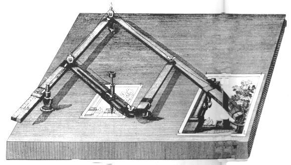
When concreting in winter conditions, with insufficient insulation or heat treatment, early freezing of concrete may occur. After thawing such concrete, he will not be able to gain the necessary strength. The damage of reinforced concrete structures is divided into three groups according to the nature of the influence on the carrying capacity. Group I - damage that practically does not reduce the strength and durability of the structure (surface sinks, voids; cracks, including shrinkage, with a disclosure of not more than 0.2mm, and also, which, under the influence of temporary load and temperature, the disclosure increases by no more than 0 , 1mm; chipped concrete without exposing reinforcement, etc.); Group II - damage, reducing the durability of the structure (corrosion-hazardous cracks more than 0.2 mm open and cracks more than 0.1 mm open, in the area of working reinforcement of prestressed spans, including along sections under constant load; cracks more than 0.3 mm open under temporary load, emptiness of the shell and chips with exposed rebar, surface and deep corrosion of concrete, etc.); Group III - damage, reducing the bearing capacity of the structure (cracks, not provided for by the calculation of either strength or endurance; inclined cracks in the walls of the beams; horizontal cracks in the joints of the slab and span structures; large shells and voids in the concrete of the compressed zone, etc. .). Damage of group I does not require the adoption of urgent measures, they can be removed by coating with current maintenance for preventive purposes. The main purpose of coatings for damage of group I is to stop the development of existing small cracks, to prevent the formation of new ones, to improve the protective properties of concrete and to protect structures from atmospheric and chemical corrosion. In case of damages of group II, the repair provides increased durability of the structure. Therefore, the materials used must have sufficient durability. Cracks in the area of the bundles of prestressed reinforcement, cracks along the reinforcement are subject to mandatory sealing. At damages of the III group restore the bearing ability of a design on a specific sign. Applied materials and technologies should provide strength characteristics and durability of the structure. For the elimination of damages of group III, as a rule, individual projects should be developed. The constant growth of monolithic construction is one of the main trends characterizing the modern period of Russian construction. However, at present a massive transition to the construction of monolithic reinforced concrete may have negative consequences associated with a rather low level of quality of individual objects. Among the main reasons for the poor quality of erected monolithic buildings, the following should be highlighted. Firstly, most of the regulatory documents currently in force in Russia were created in the era of priority development of construction from precast concrete, therefore their focus on factory technologies and insufficient development of monolithic reinforced construction are natural. Secondly, most construction companies lack sufficient experience and the necessary technological culture of monolithic construction, as well as poor-quality technical equipment. Thirdly, an effective quality management system for monolithic construction, including a system of reliable technological quality control of works, has not been created. The quality of concrete is, first of all, the compliance of its characteristics with the parameters in regulatory documents. Rosstandart approved and the new standards are in force: GOST 7473 “Concrete mixes. Technical conditions ", GOST 18195" Concretes. Rules of control and evaluation of strength. GOST 31914 “High-strength heavy and fine-grained concretes for monolithic structures” should come into force, the standard for reinforcing and embedded products should become the current one. Unfortunately, new standards do not contain issues related to the specifics of the legal relationship between construction customers and general contractors, building materials manufacturers and builders, although the quality of concrete work depends on each stage of the technical chain: preparation of raw materials for production, design of concrete, production and transportation of the mixture, laying and maintenance of concrete in the structure. Ensuring the quality of concrete in the production process is achieved thanks to a complex of different conditions: here we have modern technological equipment, availability of accredited testing laboratories, qualified personnel, unconditional fulfillment of regulatory requirements, and implementation of quality management processes. The amount of adhesion of concrete to formwork reaches several kgf / cm 2. This makes demolishing work difficult, degrades the quality of concrete surfaces and leads to premature wear of the formwork panels. Candidates tehn. Ya.P. BONDAR (TsNIIEP dwelling) Yu. S. OSTRINSKIY (NIIES) To find out how to concreting in sliding formwork for walls with a thickness of less than 12–15 ohm, the interaction forces between formwork and concrete mixtures prepared on dense aggregates, expanded clay and slag pumice were investigated. With the existing technology of concreting in the sliding formwork is the minimum allowable wall thickness. For molded concrete used ceramsite gravel Beskudnikovsky plant with crushed sand from the same expanded clay and slag pumice, made from melts Novo-Lipetsk metallurgical plant with fishing line, obtained by crushing slag lemza. Keramzitobeton brand 100 had vibroplate, measured on the device N. Ya. Spivak, 12-15 s; structural factor 0.45; bulk density of 1170 kg / m3. Slag piteum brand 200 had a vibration compaction of 15–20 s, a structural factor of 0.5, and a bulk density of 2170 kg / m3. Heavy concrete grade 200 with a bulk density of 2400 kg / m3 was characterized by a draft of a standard cone of 7 cm. The forces of interaction of the sliding formwork with concrete mixtures were measured on a test facility, which is a modification of the Kaza-Rande device for measuring the forces of a single-plane shear. The installation is made in the form of a horizontal tray filled with concrete mix. The test strips of wooden bars, sheathed on the surface of contact with the concrete mix with roofing steel strips, were laid across the tray. Thus, the test slats imitated steel sliding formwork. The slats were kept on a concrete mix under prigruzami of various sizes, simulating the pressure of concrete on the formwork, after which they fixed the efforts that cause the horizontal movement of the rails along the concrete. General view of installation is given in fig. one.  According to the results of the tests, the dependence of the interaction forces of the steel sliding formwork and the concrete mix, m, on the concrete pressure on formwork a (Fig. 2), which is linear, was obtained. The angle of the line of the graph with respect to the x-axis characterizes the angle of friction of the formwork over the concrete, which makes it possible to calculate the friction forces. The value, cut off by the line of the graph on the ordinate axis, characterizes the adhesion forces of the concrete mix and formwork m, independent of pressure. The friction angle of the formwork over the concrete does not change with an increase in the duration of the fixed contact from 15 to 60 minutes, the magnitude of the adhesion forces increases 1.5-2 times. The main increment of adhesion occurs during the first 30-40 minutes with a rapid decrease in the increment over the next 50-60 minutes. The grip strength of heavy concrete and steel formwork 15 minutes after compacting the mixture does not exceed 2.5 g / ohm2, or 25 kg / m2 of the contact surface. This amounts to 15–20% of the generally accepted value of the total interaction force between heavy concrete and steel formwork (120–150 kg / m2). The bulk of the effort comes from frictional forces. The slow growth of adhesion forces during the first 1.5 hours after compacting the concrete is explained by the insignificant number of new growths in the process of setting of the concrete mix. According to research, in the period from the beginning to the end of the setting of the concrete mix, the redistribution of mixing water between the binder and aggregates occurs in it. Neoplasms develop mainly after setting. The rapid growth of adhesion of the sliding formwork to the concrete mix begins 2-2.5 hours after compacting the concrete mix. The share of adhesion forces in the total amount of interaction forces of heavy concrete and steel sliding formwork is about 35%. The main share of the effort comes from frictional forces, determined by the pressure of the mixture, which varies with time under concreting conditions. To test this assumption, shrinkage or swelling of freshly molded concrete samples was measured immediately after compaction with vibration. During the molding of concrete cubes with a rib size of 150 mm, a textolite plate was placed on one of its vertical faces, the smooth surface of which was in the same plane as the vertical face. After compacting the concrete and removing the sample from the vibrating table, the vertical faces of the cube were freed from the side walls of the mold, and for 60-70 Min with the help of the mass, the distances between opposite vertical edges were measured. The measurement results showed that the newly-formed concrete, immediately after compaction, shrinks, the value of which is the higher, the greater the mobility of the omega. The total bilateral precipitation reaches 0.6 mm, i.e., 0.4% of the sample thickness. In the initial period after molding, the swelling of fresh concrete does not occur. This is due to the contraction in the initial stage of hardening of concrete in the process of redistribution of water, accompanied by the formation of hydrate films, creating large surface tension forces. The principle of operation of this device is similar to the principle of the conical plastometer. However, the wedge-shaped form of the indenter allows you to use the design scheme viscous bulk. The results of experiments with a wedge-shaped indenter showed that To varies from 37 to 120 g / cm2, depending on the type of concrete. Analytical calculations of the pressure of a layer of concrete mixture with a thickness of 25 ohms in the sliding formwork showed that the mixtures of the accepted compositions, after being compacted by vibration, do not exert active pressure on the covering of the formwork. The pressure in the “sliding formwork - concrete mixture” system is due to the elastic deformations of the shields under the influence of the hydrostatic pressure of the mixture in the process of its compaction by vibration. The interaction of sliding form panels and compacted concrete at the stage of their joint work is well enough modeled by passive resistance of a viscoplastic body under pressure from the vertical retaining wall. Calculations have shown that with a one-sided action of the formwork panel on the concrete mass), the displacement of part of the array but the main slip planes require increased pressure, much higher than the pressure that occurs during the most unfavorable combination of conditions for laying and compacting the mixture. When two-sided pressing of the formwork panels to the vertical layer of concrete of limited thickness, the pressing efforts necessary to displace compacted concrete ps to the main slip planes acquire the opposite sign and significantly exceed the pressure required to change the compression characteristics of the mixture. The reverse loosening of the compacted mixture under the action of bilateral compression requires such a high pressure, which is unattainable when concreting into sliding formwork. Thus, the concrete mix, which is laid according to the rules of concreting in sliding formwork with layers 25-30 cm thick, does not exert pressure on the formwork panels and is able to perceive from their side the elastic pressure that occurs during the compaction process by vibration. To determine the interaction forces arising in the process of concreting, measurements were carried out on a full-size sliding formwork model. A sensor with a membrane of high-strength phosphor bronze was installed in the molding cavity. The pressures and forces on the lifting rods in the static installation position were measured with an automatic pressure gauge (AID-6M) in the process of vibration and elevation of the formwork using an H-700 photooscyllograph with an 8-ANC amplifier. The actual characteristics of the interaction of steel sliding formwork with different types of concrete are given in the table. In the period between the end of vibration and the first rise of the formwork, a spontaneous decrease in pressure occurred. which was held unchanged until the formwork began to move upwards. This is due to the intense shrinkage of the newly-formed mixture.  To reduce the interaction forces of the sliding formwork with the concrete mix, it is necessary to reduce or completely eliminate the pressure between the formwork panels and the compacted concrete. This problem is solved by the proposed concreting technology with the use of intermediate extractable plates (“liners”) from thin (up to 2 mm) sheet material. The height of the liner is greater than the height of the cavity molding (30-35 ohms). The liners are installed in the molding cavity close to the sliding form panels (Fig. 5) and immediately after laying and compaction. The concrete is alternately removed from it. The gap (2 mm) remaining between the concrete and the formwork, after removing the shields, protects the formwork shield, which straightens after an elastic deflection (usually not exceeding 1-1.5 mm) from contact with the vertical surface of the concrete. Therefore, the vertical edges of the walls, freed from the liners, retain their shape. This allows concrete walls to be concreted in sliding formwork. The principal possibility of forming thin walls with the help of liners was tested during the construction of full-scale fragments of walls with a thickness of 7 cm, made of expanded clay concrete, slag-and-ground concrete and heavy concrete. The results of test moldings showed that light concrete mixtures better correspond to the features of the proposed technology than mixtures on dense aggregates. This is due to the high sorption properties of porous aggregates, as well as the smooth structure of lightweight concrete and the presence of a hydraulically active dispersed component in light sand.  Heavy concrete (albeit to a lesser extent) also shows the ability to maintain the verticality of freshly molded surfaces with its mobility of no more than 8 cm. When concreting civilian buildings with thin interior walls and partitions using the proposed technology, two to four pairs of liners from 1.2 to 1.6 m, providing concreting of walls with a length of 150-200 m. This will significantly reduce the consumption of concrete as compared with buildings erected according to the adopted technology, and increase the economic efficiency be their construction. Adhesion (sticking) and shrinkage of concrete, roughness and porosity of the surface affect the adhesion force of concrete with formwork. With a large force of adhesion of concrete to the formwork, the work on demoulding becomes more complicated, the labor intensity of work increases, the quality of concrete surfaces deteriorates, and the formwork shields prematurely wear out. Concrete adheres to the wooden and steel surfaces of the formwork much stronger than to the plastic. This is due to the properties of the material. Wood, plywood, steel and fiberglass are well wetted, therefore the adhesion of concrete to them is quite high, with poorly wettable materials (for example, textolite, getinax, polypropylene) the adhesion of concrete is several times lower. Therefore, to obtain high-quality surfaces, you should use cladding made of PCB, getinaks, polypropylene, or use waterproof plywood treated with special compounds. When the adhesion is low, the surface of the concrete is not broken and the formwork leaves easily. With increasing adhesion, the layer of concrete adjacent to the formwork collapses. This does not affect the strength characteristics of the structure, but the quality of the surfaces is significantly reduced. To reduce the adhesion can be applied to the surface of the formwork with aqueous suspensions, water-repellent lubricants, combined lubricants, lubricants - retarders concrete. The principle of action of aqueous suspensions and water-repellent lubricants is based on the fact that a protective film is formed on the surface of the formwork, which reduces the adhesion of concrete to the formwork. Combined lubricants are a mixture of retarders of concrete and water-repellent emulsions. In the manufacture of lubricants they add sulfite-yeast bard (SDB), mylonaph. Such lubricants plasticize the concrete of the adjacent zone, and it does not collapse. Lubricants - retarders of concrete - are used to obtain a good surface texture. By the time of stripping, the strength of these layers is somewhat lower than the bulk of the concrete. Immediately after stripping, the concrete structure is exposed by washing it with a stream of water. After such a wash, a beautiful surface is obtained with a uniform exposure of coarse aggregate. Lubricants are applied to the formwork panels prior to installation in the design position by pneumatic spraying. This method of application ensures uniformity and constant thickness of the applied layer, as well as reduces the consumption of lubricant. For pneumatic application apply sprayers or fishing rods sprayers. Greater viscous greases are applied with rollers or brushes. |

 Observed with improper installation or offset formwork or reinforced frame, no gaskets.
 During the care of the concrete, it is necessary to create such temperature-wet conditions that would ensure the preservation in the concrete of the water necessary for the hydration of cement. If the curing process takes place at a relatively constant temperature and humidity, the stresses that occur in the concrete due to volume changes and are caused by shrinkage and temperature distortions will be insignificant. Typically, the concrete is covered with plastic wrap or other protective coating. In order to prevent it from drying out. The overdried concrete has much lower strength and frost resistance than normally hardened, many shrinkage cracks arise in it.
Popular:
New
- Markup definition. Planar marking. Types of markup. Questions for self-test
- Pipe bending machines Various variations of pipe bending machine
- Safety during filing
- What should be the sharpening angle of the scriber
- Drawing on preparation of contours of future product
- Modern ways of cutting metal and its defects
- Kerner - so that the drill does not slip off!
- Objects of inanimate nature Examples of the influence of inanimate nature factors on plants
- Finishing joinery
- Block breakdown in AutoCAD - simple and effective teams from practitioners