Site sections
Editor's Choice:
- Court decision on recovery from the management company of the amount of damage to the gulf of the apartment
- Living room and children in the same room: options for partitions
- Top sofa upholstery rating: customer reviews
- Expansion joints in buildings
- Chaber - what is it and its purpose
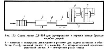
- Sharpening wood cutters: manual work, using grinding wheels and a grinding machine
- Belts and sandriks, crackers and volutes - secret codes of architecture on the example of the old Saratov Sandriks in architecture
- Surface grit - tooling work
- Maximum load on the balcony slab: how much can a balcony withstand in a panel house?
- Projects: symbols on drawings for water supply and sewage
Advertising
| Filter gas designation on the diagram. Alphanumeric designations of gas pipelines. Types of documents BTI |
|
STATE STANDARD OF THE UNION SSR SYSTEMSA DESIGN DOCUMENT FOR CONSTRUCTION GAS SUPPLY. WORKING DRAWINGS GOST 21.609-83 STANDARDS PUBLISHING HOUSE Moscow STATE STANDARD OF THE UNION SSR This standard establishes the composition and design rules for working drawings of internal gas supply devices * for buildings and structures of all industries and national economy. * Internal gas supply devices are hereinafter referred to as gas supply. 1. GENERAL PROVISIONS1.1. Working drawings of gas supply are performed in accordance with the requirements of this standard and other standards of the design documentation system for construction, as well as the norms of gas supply design. 1.2. The composition of the working drawings of gas supply (the main set of working drawings of the brand FGP) include: general data on the working drawings; drawings (plans, sections and views) of the location of gas pipelines, gas instrumentation and gas equipment **; gas supply schemes; drawings (plans, sections, types and diagrams) of gas installations; sketch drawings of common types of atypical devices and gas supply structures ***. ** Gas instrumentation and gas equipment are hereinafter referred to as equipment. *** Sketch drawings of general types of atypical devices and structures are hereinafter referred to as drawings of general types. To the main set of working drawings of the GSV brand, the specification of the equipment and the list of material requirements in accordance with GOST 21.109-80 are performed.
1.4. The diameter and thickness of the wall of the pipeline indicate the line of the leader. For gas pipelines made of steel water and gas pipes indicate the diameter of the nominal passage and wall thickness. For gas pipelines from steel electrowelded and other pipes indicate the outer diameter and wall thickness. In the case when the alphanumeric designation of a gas pipeline is indicated on the shelf of the leader line, its diameter and wall thickness are indicated under the shelf of the leader line. 1.5. The risers of gas pipelines are designated by the brand consisting of the letter designation “St” and, through a hyphen, the serial number of the riser within the building (structure), for example St-1, St-2. 1.6. Conditional graphic images of valves (shut-off, regulating and safety) and equipment are accepted according to state standards, taking into account the additional images given in.
2. GENERAL DATA ON WORKING DRAWINGS2.1. The general data of the main set of working drawings of the FGP brand in addition to the data provided for by GOST 21.102-79 include: Key indicators for working drawings of the FGP brand
_________ * The characteristic of the gas used is indicated in a note. 3. DRAWINGS OF THE GAS PIPELINE
| ||||||||||||||||||||||||||||||||||||||||||||||||||||||||||||||||||||||||||||||||||||||||||||||||||||||||||||||||||||||||||||||||||||||||||||||||||||||||||||||||||||||||||||||||||||||||||||||||||||||||||||||||||||||||||||||||||||||||||||||||||||||||||||||||||||||||||||||||||||||||||||||||||||||||||||||||||||||||||||||||||||||||||||||||||||||||||||||||||||||||||||||||||||||||||||||||||||||||||||||||||||||||||||||||||||||||||||||||||||||||||||||||||||||||||||||||||||||||||||||||||||||||||||||||||||||||||||||||||||||||||||||||||||||||||||||||||||||||||||||||||||||||||||||||

|
1. Scheme of the gas network in a semi-detached house 2. The diameters in the gas network supplying the meters with one apartment with a bathroom on the floor; with two apartments on the floor. 3. Sizes of niches for 1 - 3 gas meters. OKF - clean floor level. 4. Niche for 1 electric and 1 gas meter. 5. Niche for 1 electric and 1 gas meter. |
 |
|
6. The room of inputs of engineering networks (DIN 18012) with the turning on and locking devices for strong and weak currents, gas, water supply and the sewerage. 7. Section of the premises of utilities engineering networks. 8. Layout of premises utilities utilities. |
The following devices do not require connection to the gas ducts:
1. All types of gas cookers and gas refrigerators.
2. Heaters with a capacity of up to 10 liters in rooms with a volume of at least tenfold gas consumption.
3. Tanks for boiling linen and washing machines with a gas consumption of up to 2.5 m3 / h in rooms with a volume of at least tenfold gas consumption.
4. Gas heaters installed at the exterior walls with exhaust holes in the wall.
In all other cases (water heaters, laundry boilers and larger washing machines, heating stoves, etc.), gas appliances must be connected to gas ducts.
The supplier is obliged to install a fuse on the outlet nozzle, which eliminates the possibility of condensation and the return of exhaust gases. The automatic dimmer valve of the Dirmeyer system with thermal regulation (Fig. 2) protects the premises from cooling through the flue duct and from violation of the thrust when the exhaust duct is mixed (for off-gases from gas and solid-fuel appliances); in addition, such a valve reduces noise. The carbon dioxide content in the air of rooms designed for temporary stay of people (bathroom, kitchen, etc.) should not exceed 0.4%; in rooms for a long stay (common rooms and bedrooms) about 0.15%.
Flues
No more than three firing points are allowed to be connected to the standard-section gas duct of 135 x 135 mm in brick walls: do not make gas ducts with a cross section of more than 200 x200 mm; firing points operating on solid fuel and gas, if possible, do not attach to one gas duct. Ducts should be located in warm places to avoid condensation on the cold walls. On the top of the flue, you must install a wind cap. On flat roofs, ducts should be no less than 50 cm above the parapet (Fig. 3 and 4).
Gas consumption: for taking a shower for 5 minutes with a water heater with a capacity of 5 liters - 0.25 m3; for heating the room for 15 minutes - 0.25 m3.
Liquefied gas (non-toxic gases - propane, butane, etc.) is used for gas supply in remote areas.
Specifications for liquefied gas (TRF 1969):
| Capacity | Mass in the filled state, kg | Diameter, mm | Height mm | Height with valve, mm |
| Small cylinders | 3 | 205 | 320 | 420 |
| 5 | 230 | 400 | 500 | |
| 11 | 300 | 500 | 600 | |
| Large cylinders | 22 | 270 | 1100 | 1200 |
| 33 | 320 | 1200 | 1300 |
Places for installation of cylinders: small cylinders can be installed in any room except sleeping rooms; large cylinders - outside the building in a lockable metal cabinet or in a room with a separate external entrance; 1 kg of liquefied gas (3 m3 of natural gas) gives about 5000kkal.
Liquefied gas costs almost 1/3 more than gas from the city network.
The diameters of pipes with liquefied gas are significantly less than the diameters of gas pipes of the city network due to increased pressure.
When a property, for example, an apartment building, is put into operation, it is necessary to inventory it in order to legally fix the available space. To this end, employees of the Bureau of Technical Inventory measure the premises. And further, on the basis of the data obtained, make up the floor plan of the building.
However, to coordinate the redevelopment of the floor plan of the building is not needed, it is enough to have a floor plan of the apartment or the non-residential premises, which is planned to alter. Thus, it can be said that the floor plan or simply the BTI plan is a document of information and reference type, where, taking into account the measurements, the actual state of the apartment (non-residential premises) is presented.
The BTI plan shows the exact size of the rooms and graphically marks the following elements:
- main walls and partitions;
- balconies and loggias;
- door and window openings;
- sanitary appliances and cookers;
- ventilation.
All of these elements are marked in the BTI floor plan.
Types of documents BTI
The following types of documents issued by the Bureau of Technical Inventory are used to coordinate redevelopment.
Floor plan and explication
You can learn more about what these documents are, how and where they can be ordered from a separate articles . Here we only note that these are the simplest documents of the BTI, in which the minimum information about the object is presented.
The floor plan is a diagram of the object, presented as a drawing with special symbols. At the entrance to the apartment on the drawing indicated her number. In addition, the sheet contains a stamp of the BTI office, which issued the document. Also, the BTI floor plan contains information on the legal address of the building and the floor on which the room is located, as well as the date of its last survey.
An explication is attached to the floor plan, which lists and assigns all the premises of the object - residential and auxiliary - with an indication of their area and height of ceilings.

Floor plan with explication
Thus, the floor plan with explication is two sheets of the same format, one of which reflects the floor plan in the form of a drawing, and the other shows a table with the characteristics of the rooms and rooms.
Technical passport BTI
The technical passport is a document that is specifically designed to coordinate redevelopments.
Technical passport with BTI plan
About him we also have a separate one. But speaking in general, this is a more detailed document that, in addition to the floor plan and explication, contains information about the house where the room is located (series, material of walls and floors, number of floors of the building, number of apartments, year of construction, etc.) address plan, etc.
Floor plan with explication before redevelopment
This document is used to legitimize the redevelopment that has already been made, if illegally carried out changes are indicated in the BTI documents with red lines. Read more about this.
In general, this document is similar to a floor plan with explication, but it has a special mark “before redevelopment” or “before re-equipment”.


Floor plan with explication before redevelopment
Any room consists of structural elements that have their own name, purpose, size, shape and other characteristics. On the plans of the BTI, they are reflected in the form of conventional graphic symbols, which are not always clear to the owners of the premises.
And since everyone who has decided to redevelop his apartment and wants to make it legally will need to deal with some of these documents, it is important to be able to figure out how and what is indicated on them. Therefore, we will further analyze the notation on the BTI plans.
Description of designations on BTI plans
Immediately, we note that the designation BTI does not depend on the type of document. That is, one or another element of the drawing is denoted in the same way both in the data sheet and on the floor plan.
First of all, the owners are interested in such a question, how is the designation of the bearing walls on the BTI plan? Many consider that on the drawing thick walls mark capital walls, and thin - non-bearing partitions. But this is not always the case.
Therefore, it is impossible to determine according to the BTI plan which walls are bearing and which are non-bearing. In any case, it certainly can not make the man in the street themselves, if only he turns for help to a specialist.
If the room was completed uncoordinated redevelopment , which became known to the BTI, then after the necessary measurements by an employee of the Bureau of Technical Inventory, all changes made in the drawing will be marked with red lines.
Doorways are indicated as follows: within the boundaries of the line, two small marks in the form of parallel dashes are applied perpendicularly to indicate the partition. In the presence of a door leaf between them, another parallel line extends beyond the wall boundary. That is the designation of the door on the BTI plan.
Similarly, information on the presence and location of window openings is entered into the floor plan. The thickest lines in the drawing are the facade walls, on which the windows are marked by two parallel lines with perpendicular constraints on both sides, showing their width.
The numbering and area of the room are displayed as a fractional number, where the numerator is the room number and the denominator is its area.
In addition, the plans for BTI is applied to the location of plumbing and stoves in the "wet" areas of the apartment. Most often, it is possible to guess which plumbing fixtures are indicated in the drawing along the contours of the geometric shapes that designate them. And the designation of the electric stove on the BTI plan can also be guessed.
For reference: furniture, refrigerator, air conditioner, washing machine and dishwasher, heated towel rail, oven, etc. not indicated on the BTI floor plan. Also has no designation in the passport BTI flooring material in the premises.
The interpretation of the notation on the BTI plan is the easiest to give with specific examples.

equipment.If you need to find out the symbols of BTI, as well as require assistance in the development of project documentation and the coordination of redevelopment in government agencies, our employees are always ready to help.
Working drawings
GOST
21.609-83
By the Decree of the USSR State Committee on Construction Affairs dated August 17, 1983 No. 203, the introduction date was set
from 01/01/84
This standard establishes the composition of the right to design working drawings for internal devices for gas supply * and the construction of all branches of industry.
* Inside nnye devices gas supplies are hereinafter referred to as gas supply.
1. GENERAL PROVISIONS
drawings (plans, sections, types and diagrams) of gas installations;
|
(0,05 kgf / cm 2) |
|
|
c) wed day pressure more |
|
|
5 kPa (0.05 kgf / cm 2) |
|
|
up to 0.3 MPa (3 kgf / cm 2) |
|
|
2. Wireline purge |
|
|
3. Drain line niya |
In the case when on the shelf callout lines indicate the letter nn The o-digital designation of the pipeline, its diameter and wall thickness indicate under the shelf callout lines.
1.5. Gas pipeline risers are designated by the brand name "St" and, through a hyphen, the serial number of the riser within the building (structure), for example St-1, St-2.
1.6. The conditional graphic depicts reinforcement (shut-off, regulating and safety) and the equipment is accepted according to the state standard, taking into account the additional images given in.
|
Name |
Picture |
|
1. Gas meter |
|
|
2. Household double-burner gas stove |
|
|
3. Household four-burner gas stove |
|
|
4. Gas heating appliance |
|
|
5. Furnace heating and cooking |
|
|
6. Gas fireplace |
|
|
7. Pressure Regulator |
|
|
8. Safety shut-off valve |
|
|
9. Control Regulator |
2. GENERAL DATA ON WORKING DRAWINGS
2.1. The general data of the main set of working drawings of the FGP brand in addition to the data provided for include:
Key indicators for working drawings of the FGP brand

_________
* The characteristic of the gas used is indicated in a note.
3. DRAWINGS OF THE GAS PIPELINE
AND EQUIPMENT
3.1. Drawings for the location of gas pipelines and equipment are performed according to -79, taking into account the requirements of this standard.
3.2. Plans, cuts and types
3.2.1. Plans, sections and views are carried out on a scale of 1: 100 or 1: 200, nodes and fragments of plans, sections and types are carried out on a scale of 1:10 - 1: 100.
In case of small buildings or structures, when the execution of fragments is impractical, plans, sections and views are allowed to be carried out at the scales established for the fragments.
3.2.2. Pipelines located one above the other on the plans are conventionally represented by parallel lines.
3.2.3. Pipelines, equipment and fittings on plans, sections and views are indicated by conventional graphic images, and equipment for which conventional graphic images are missing are simplified graphic images.
Pipelines with a diameter of 100 mm and more on the fragments and nodes represent two lines.
3.2.4. On the plans, sections and views indicate: the coordination axis of the building (structure) and the distance between them (for residential buildings - the distance between the axes of the sections);
building structures and equipment to which gas-air is supplied and from which combustion products are diverted. Building structures and equipment indicate in continuous thin lines;
level marks for clean floors and main sites;
dimensional bindings of gas installations and equipment, inputs (outputs) and risers of gas pipelines to coordination axes or elements of building structures;
sizes of operational passes;
level marks or height adjustment installation of devices (if necessary).
The plans also indicate the names of the premises (types of premises for residential buildings) and the category of production for explosive, explosion-fire and fire danger (in a rectangle of size 5 ´ 8 mm), and on the cuts and types - the marks of the levels of the axes of gas pipelines and the top of the waste gas pipeline (candles).
The names of the premises and the category of production for explosive, explosion-fire and fire danger are allowed to be given in the explication of the premises in form 2 -80.
4. SCHEMES OF GAS SUPPLY
For residential and household buildings, instead of a graphical image of the connected equipment, it is allowed to indicate it.
Heck. one
Heck. 2
Pr m p clearance c we are given on
|
GAS NETWORKS. SYMBOLS
Symbols of gas equipment. Explanation of accepted terminology. Color pipelines on the drawings. The diameters of the supply pipelines and gas costs for different devices. Gas ducts. Technical conditions for liquefied gas. Device of gas ducts.
| 1. The intersection of the gas network lines with open wiring 2. Recessed wiring 3. Changing the diameters of the gas network pipes 4. Air duct 5. Pulse pipe 6. Grounding 7. Gas hose 8. Ceiling lamp with indication of the number of horns 9. Fixed wall lamp 10. Wall Mobile lamp 11. Venting pipe 12. Flue 13. Gas stove with three burners 14. Gas stove with oven 15. Refrigerator 16. Gas heating stove 17. Flow-through water heater 18. Capacity water heater 19. Install the appliance in the opening with 20. Installation of the device in the opening with a gap of 21. Water bag, water tank 22. Wall mounted gas heater 23. Gas meter |
Explanations to the accepted terminology:
gas appliances named devices that do not require connection to the ducts;
gas firing points called devices that are connected to the ducts;
the instructions “up to the counter” and “behind the counter” correspond to the direction of gas movement in the network.
Gas consumption: for every 1 m3 of air volume in a heated room for the heating season (September - May) with a long fire (in residential buildings) 18 - 25 m3 of gas, with a periodic fire (in commercial premises) - 10 - 15 m3 of gas.
The color of the pipelines in the drawings: gas pipelines - yellow, cold water pipelines - light blue, hot water pipelines - red.
The diameters of the supply pipelines and gas costs for different devices:

1. Scheme of the gas network in a semi-detached house
2. The diameters in the gas network supplying the meters with one apartment with a bathroom on the floor; with two apartments on the floor.
3. Sizes of niches for 1 - 3 gas meters. OKF - clean floor level.
4. Niche for 1 electric and 1 gas meter.
5. Niche for 1 electric and 1 gas meter.

The following devices do not require connection to the gas ducts:
1. All types of gas cookers and gas refrigerators.
2. Heaters with a capacity of up to 10 liters in rooms with a volume of at least tenfold gas consumption.
3. Tanks for boiling linen and washing machines with a gas consumption of up to 2.5 m3 / h in rooms with a volume of at least tenfold gas consumption.
4. Gas heaters installed at the exterior walls with exhaust holes in the wall.
In all other cases (water heaters, laundry boilers and larger washing machines, heating stoves, etc.), gas appliances must be connected to gas ducts.
The supplier is obliged to install a fuse on the outlet nozzle, which eliminates the possibility of condensation and the return of exhaust gases. The automatic dimmer valve of the Dirmeyer system with thermal regulation (Fig. 2) protects the premises from cooling through the flue duct and from violation of the thrust when the exhaust duct is mixed (for off-gases from gas and solid-fuel appliances); in addition, such a valve reduces noise. The carbon dioxide content in the air of rooms designed for temporary stay of people (bathroom, kitchen, etc.) should not exceed 0.4%; in rooms for a long stay (common rooms and bedrooms) about 0.15%.
Flues
No more than three firing points are allowed to be connected to the standard-section gas duct of 135 x 135 mm in brick walls: do not make gas ducts with a cross section of more than 200 x200 mm; firing points operating on solid fuel and gas, if possible, do not attach to one gas duct. Ducts should be located in warm places to avoid condensation on the cold walls. On the top of the flue, you must install a wind cap. On flat roofs, ducts should be no less than 50 cm above the parapet (Fig. 3 and 4).
Gas consumption: for taking a shower for 5 minutes with a water heater with a capacity of 5 liters - 0.25 m3; for heating the room for 15 minutes - 0.25 m3.
Liquefied gas (non-toxic gases - propane, butane, etc.) is used for gas supply in remote areas.
Specifications for liquefied gas (TRF 1969):
Places for installation of cylinders: small cylinders can be installed in any room except sleeping rooms; large cylinders - outside the building in a lockable metal cabinet or in a room with a separate external entrance; 1 kg of liquefied gas (3 m3 of natural gas) gives about 5000kkal.
Liquefied gas costs almost 1/3 more than gas from the city network.
The diameters of pipes with liquefied gas are significantly less than the diameters of gas pipes of the city network due to increased pressure.


9. Diagram of a gas network connected to compressed gas cylinders
Created on the basis of:
1. STO GAZPROMREGIONGAZ 1.2-2009 "Graphic display of gas distribution facilities and related communications."
2. GOST 2.780-96 “Unified system for design documentation. Symbols conditional graphic. Air conditioning conditioners, hydraulic and pneumatic tanks. "
3. GOST 2.784-96 “Unified system for design documentation. Symbols conditional graphic. Elements of pipelines.
4. GOST 2.787-71 “Unified system for design documentation. Conditional graphic designations in schemes. Elements, devices and devices of the gas chromatograph system ".
5. GOST 21.609-83 “System of project documentation for construction. Gas supply. Internal devices. Working drawings".
6. GOST 21.404-85 “System of project documentation for construction. Automation of technological processes. Designations conventional instruments and automation tools in the schemes ".
7. GOST 21.206-93 "System of project documentation for construction. Symbols of pipelines ".
| Read: |
|---|
Popular:

New
- Open lesson "editing, bending"
- Installation of staircases and platforms: general information
- Repair of pipes of water supply in the apartment Repair of steel pipes
- Markup definition. Planar marking. Types of markup. Questions for self-test
- Pipe bending machines Various variations of pipe bending machine
- Safety during filing
- What should be the sharpening angle of the scriber
- Drawing on preparation of contours of future product
- Modern ways of cutting metal and its defects
- Kerner - so that the drill does not slip off!