Site sections
Editor's Choice:
- Installation options for drywall in the bathroom
- Court decision on recovery from the management company of the amount of damage to the gulf of the apartment
- Living room and children in the same room: options for partitions
- Top sofa upholstery rating: customer reviews
- Expansion joints in buildings
- Chaber - what is it and its purpose
- Sharpening wood cutters: manual work, using grinding wheels and a grinding machine
- Belts and sandriks, crackers and volutes - secret codes of architecture on the example of the old Saratov Sandriks in architecture
- Surface grit - tooling work
- Maximum load on the balcony slab: how much can a balcony withstand in a panel house?
Advertising
|
\
Documents \
For technology teacher and job training
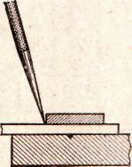
When using materials from this site - and placement of a banner - OPTIONAL !!! Materials sent by Glebov A.A. teacher of technology and labor training MOU "Veselolopanskaya secondary school" Lesson number 17-18.Marking wood blanks.Purpose:teach students how to mark the details of wood. Equipment:wooden blanks, drawings, marking tools (pencils, rulers, squares, compasses, gauges, templates, etc.). During the classes I. Repetition of the material covered. 1. Talk on: "Name the assignment of the flow chart. "What is called a stock? "What is called a process operation? 2. Posting topics and objectives of the lesson. Ii. Presentation of program material. 1. Introduction to the topic of the lesson. Teacher. Do you have material from which I would like to make a conceived product. There are tools to get started: cut, drill, trim, etc. "Is it possible to proceed? "Will you have a good, high-quality, beautiful job? "Why? (Listened to the views of students.) The guys, to embody any conceived case and get such a product that would be pleasing to the eye, consistent with the required size and proper processing, you need to think carefully about everything. What do you think, where to start? (Presumptive answers from students.) Before making parts of the desired shape, they are marked out using measuring and marking tools. Write down what the term "markup" means. Markup - this drawing contour lines on the workpiece. When marking parts of rectangular shape, a ruler and a square are used. The teacher demonstrates the techniques of rectangular marking. (See Appendices, Fig. 17.)
2. Sequence of markup actions. 1 .Before marking, one of the edges of the workpiece is cut down or pressed exactly in a straight line. 2 Parallel marking lines can be made using surface gauge. (See Appendices, fig. 18, 19.)
3. Circles and arcs are drawn with a compass on the marked blank. Then the center is marked. 4. The radius is plotted on the ruler. 5 .Apherding the radius a circle is outlined. Consider a special kind of markup, which is pattern markup. Pattern marking is used if it is necessary to manufacture several identical parts of complex shape. Templates for these identical parts are made of wood, metal, plastic. What do you think the role of patterns in the overall manufacturing process? (Student answers.) Layout on the template allows you to quickly and accurately draw the desired shape of the part. The teacher shows the acceptance of markup on the template. III.Practical work. Execution of tasks: 1. Using the marking tools, mark up the workpiece parts according to the drawings proposed by the teacher. 2. Mark the blank according to the template proposed by the teacher. IV.The outcome of the lesson. Evaluation of the practical work of students. The teacher marks the best work. Lesson number 17-18.MARKING OF WOOD PLANTSLiked? Thank us, please! For you, it's free, but for us - a big help! Add our site to your social network:(sequence and tricks) Marking can be of two types: a) rough - for cutting boards, bars into rough (blanking) blanks, in which the marking is carried out with a certain margin in length, width and thickness; b) finishing - for processing blanks in order to obtain parts whose dimensions are given by the drawings. The draft marking is intended to increase the useful yield of the blanks. There are no high demands on the accuracy of the draft markup, so it is done with the help of templates or a ruler with a soft pencil. Finishing marking is performed with the required accuracy with the help of metal scale lines with a scale division of 1 or 0.5 mm and a sharply sharpened 2T-4T pencil or metal awl (scriber). The scriber is especially handy when marking up varnished surfaces. Before proceeding with the marking, it is necessary to check the quality of the blanks selected by us for marking, to verify the dimensions with those indicated on the drawing. Mark the faces with a wavy line, sort the blanks into groups. Each group should contain blanks, marked up or jointly (group marking, for example, table legs), or separately (individual marking). Determine the operating sequence of marking on the workpiece. Then the workpiece to be marked in the first place, laid on the workboard bench. The front sides of the blanks should be oriented in one direction, as a rule - towards the worker. The sequence of marking markings: a) transverse, b) fractional (longitudinal), c) inclined (at an angle), d) circumference and rounding. Before applying marking marks perform a breakdown, i.e. put on a scale ruler tags in the form of points or strokes. The breakdown is always started from the measuring base, which, as a rule, serves as the edge or face of the workpiece, or, finally, specifically for this, the applied risk. During the breakdown, the number of intermediate sizes should be reduced as much as possible and, if possible, measure from one base. In other words, the breakdown should be conducted not by adding the size to the size (butt), which leads to the accumulation of the total error, but by splitting a large segment (unchanged in the process of splitting) into smaller ones corresponding to the drawing. The transverse risks are applied with a pencil over the square, for which the square of the square is placed on the front side of the blank (usually it is the edge), and the block of the square is pressed against the other front side of the blank and applied with a pencil. When applying scratches, the base of the square should lie flush with the workpiece along its entire length, and the pencil should have a double slope - one away from the ruler and the other in the direction of drawing the line. The risk will be parallel to the ruler and is clearly visible if: a) the pencil fits tightly to the ruler, b) the ruler fits tightly to the workpiece, c) the pencil is sharply sharp, d) the risk is held confidently, firmly, but only once. Also carry out the application of equity markings using gauge and comb, and the comb applied risks in both the longitudinal and transverse directions, as well as on the end planes. It is possible to carry the surface gage and the comb on oneself and from oneself, and the depth of the risok shall be between 0.3 - 0.5 mm. Oblique risks are carried out on triangles, junk, small scale scaler or patterns. The procedure is the same as when applying transverse scratches. Work compasses all understandable. We can only say that the center of the circles is marked with perpendicular risks performed from the front sides using a scale ruler or surface gauge. Marking requirements are determined by its accuracy and compliance with the drawing. The accuracy of marking on the scale bar should be in the range of 0.25 - 0.5 mm. When group marking blanks produced a comparative control, i.e. one of the marked blanks is carefully compared with the drawing, marked it as a sample. In the future, it is used in markup and control. Theme of the lesson: "Marking wood blanks" Tasks of the lesson:
  STRUCTURE OF THE TREE
 Graphic documentation
 Markup - this drawing contour lines on the workpiece.  RIDDLES 1. I love straightforwardness. And the very direct. Make a straight line I help everyone. 2. A straight line, well, Himself draw sumei-ka! This is a complex science! It is useful here ... 3. The eye will not help I need the exact size. Where necessary, put tags Via...  Marking and measuring tools
 
1. Before marking, one of the edges of the workpiece is cut or struck exactly in a straight line. This edge is called the base plate. 2. Parallel marking lines can be made using surface gauge.  Markup Sequence 3. With the help of a compass, circles and arcs are drawn on the marked blank. Then the center is marked. 4. Radius is deposited on the ruler. 5.By deferred radius a circle is outlined.  Marking board Harmonization Rules   Routing № payment order Sequence of operations Graphic image Build a drawing. Choose a plywood blank 10-12 mm thick and mark the contour of the product. Tools and fixtures Drawing, template, pencil  Performance of tasks 1. Construction drawing. 2. Using the marking tools, mark the workpiece blank on the template.  Workplace organization
 Causes of marriage a) inaccuracy of the measuring instrument; b) non-compliance with markup techniques; c) carelessness of the worker.  Homework
Preparing for markup. Before proceeding with the markup, carefully check the workpiece: if there are shells, cracks, broken corners and other defects. Then the workpiece is cleaned of dirt and dust. Further, they study in detail the drawing of the future part and outline the order of marking: they determine in which position the part will be mounted on the plate and in what sequence the marking lines will be drawn. In order to choose the correct path marking, it is necessary to clearly represent the purpose of the marked up part, her. role in the car. Therefore, in addition to the drawing of the marking part, it is also necessary to study the assembly drawing and become familiar with the technology of manufacturing the part. Select base when marking. The correct choice of the base when markup predetermines the quality of the markup. The choice of marking bases depends on the design features and technology of manufacturing parts. Base is selected, guided by the following rules: if there is at least one treated surface on the workpiece, it is taken as a base; if not all surfaces are processed, then the surface to be treated is taken as the base; if the outer and inner surfaces are not treated, then the outer surface is preferably taken as the base; all sizes are applied from one surface or from one line, taken as a base. After the base has been mapped out, the marking order, the location and the installation of the marking part on the plate are determined and the necessary marking tools and fixtures are selected. Installation of the workpiece on the marking plate. Before installing the workpiece on the marking plate, those places where the marking risks will be applied are painted with chalk, paint, varnish or copper sulphate. When installing only the first position of the workpiece on the plate is independent, and all other provisions depend on the first. Therefore, the first position of the workpiece must be chosen so that it is convenient to start marking from the surface or the center line adopted for the base. The workpiece is not installed on the plate in an arbitrary position, but in such a way that one of its main axes is parallel to the surface of the marking plate. There are usually three such axes on the workpiece: in length, width and height. Details of large dimensions that cannot be turned over are marked with reamers and marking squares. Install reismas on the marking plate and. moving it, put marking lines. Marking marks. With the spatial marking of blanks, it is necessary to apply horizontal, vertical and oblique risks. These denominations are retained even after turning the workpiece during the marking process. If, for example, the risks during the initial position of the workpiece were held horizontally, then, although they turned vertical after the workpiece was rotated 90 °, so that there was no confusion, they continue to be called horizontal. In addition to the main marking risks, parallel to them at a distance of 5–7 mm, they carry out control pencils in colored pencil, which serve to verify the installation of the workpiece during further processing, as well as for processing in cases where the risk has somehow disappeared. When marking on the slab, horizontal risks are drawn with a reamer set to the appropriate size. Reismas move parallel to the surface of the marking plate, slightly pressing it with the base to the plate. At the same time, the needle of reismas should be directed obliquely to the marked surface in the direction of movement at an angle of 75 - 80 °. Press the needle on the workpiece evenly. The marking of vertical scratches can be done in three ways: by marking square, reismas and turning the workpiece by 90 °, flight from the marking boxes without turning the workpiece. The inclined lines are applied by the scriber by rotating the part along the protractor mounted at the required angle. The marking with the help of dividing heads (rotary marking table designed by S. V. Lastochkin) (Fig. 303). Round table 7 with T-shaped grooves 8 for fixing blanks has a 360 ° limb. It can be equipped with a three-jaw chuck for centering and clamping cylindrical blanks. The angle of inclination of the axis 7 of the table is counted using sector 2 with a scale of 3 ° 180 ° and a nonius 5, located on the bevel of the window of the housing 6. On the table it is possible to mark the blanks of parts of various shapes. In this case, the three-jaw chuck is removed, and the billet is fixed with special tacks installed in the T-shaped grooves. For accurate and fast installation of angles through each degree, special fixers 4 turns relative to both axes of rotation are provided in the device. The marking of cylindrical parts. The workpiece is installed on a plate on one or two prisms and the horizontality of the generatrix of the cylindrical surface relative to the surface of the marking plate is checked (Fig. 304, a). Short cylindrical parts mounted on a single prism. The keyway marking on the roller must be performed in the following order: study the drawing; check the workpiece; clean the marked places on the roller; to paint with copper sulfate the end (Fig. 304, 6) of the roller and part of the side surface on which risks will be applied; find the center on the end using the center-finder (or reismas); install a roller on the prism and check its horizontal position; put on the end of the roller horizontal line (Fig. 304, a), passing through the center; turn the roller 90 ° and check the verticality of the drawn line on the square; put a horizontal line on the end of the flight; draw a line on the lateral surface of the roller with Reismas; draw two lines on the side surface corresponding to the width of the keyway, and at the end of the keyway to the depth of the groove; turn the roller keyway up and draw on the end of the line indicating the depth of the keyway, nakernit contours keyway. Pattern markup is used in case of wear or breakage of parts and in the absence of a drawing for the manufacture of a new one. In such cases, the sample is a worn or broken part. If the part is flat, then after thorough cleaning it is superimposed on the workpiece and stroke lines are laid on it. In those cases where it is impossible to impose a sample on the workpiece, it is placed side by side and all dimensions are transferred from it to the workpiece with reismas. When removing the dimensions from the sample, take into account the wear of the sample (the old part), and also check whether it is not damaged, if it is warped, if the protrusions are broken off, etc.
Marking on site is made in cases where, by the nature of the compounds, it is required to assemble parts on site. For this, one of the parts is marked, holes are drilled in it; in the second part, the holes are drilled after the first is laid on it, which is like a template with respect to the second. Rational markup techniques. When working with flightmasom, each installation of the scriber in height takes a lot of time. When marking a batch of identical parts, several flight points are used that are pre-set to a certain size. Scriber need to set in a certain position only once, and then consistently transfer them to all marked blanks. From time to time the installation of the scriber should be checked. If there is only one reisma at the disposal of the locksmith, it is recommended that you first transfer one set size (Fig. 305) to all the workpieces, then the second, third, and so on. Coordinate markings. The basis of these devices is the coordinate method, which allows some geometrical elements (for example, a marked contour) to be determined relative to others (for example, the installation base of the part) using numbers. These devices are universal, significantly accelerate the markup, increase its accuracy and productivity. Coordinate marking machine model BE-SHA is designed for preliminary measurement and marking of body parts (castings). With low accuracy requirements, the machine can be used to measure deviations of the basic geometrical parameters (diameters, center-to-center distances, angles, axial positions, parallelism, perpendicularity, etc.) of the machined parts. The flat rotary table freely established on a plate surface is included in the package of the car. The part to be marked or measured is installed on the faceplate of the turntable and is set by adjusting the jacks and turning the faceplate. The movement of the horizontal carriage with the stand and the rotation of the faceplate of the table with the part during measurement and marking can be carried out manually or with the help of electric motors. The set of marking-measuring tools contains probes with spherical tips, an indicator, special compasses, spring-loaded incisors with holders that allow you to feel and draw lines or circles on different surfaces of castings and finished parts. The machine is equipped with a digital printing device and a keyboard computing machine. On the panels of digital display devices, measurements of twice the magnitude of displacement (diameter), the installation of initial zero counts in any position of the measuring nodes, as well as a set of set base coordinates are provided. The use of these systems facilitates the processing of measurement results, simplifies the measurement of the diameter and ensures that the center is found without complicated calculations. Most types of markings can be successfully performed on coordinate drilling machines, several models of which are based on conventional desktop drilling machines. Such machines are equipped with cross calipers with limbs and vernier, allowing you to move the table by a specified amount in two mutually perpendicular directions, which is necessary when marking in the coordinate system. Counting devices. When marking, it is necessary to perform various mathematical calculations: calculate chord lengths corresponding to specified central corners, divide circles into different numbers of parts, solve right triangles, find trigonometric functions, determine coordinates of intersection points of various surfaces, etc. The use of calculating devices increases efficiency and quality of work. Coordinate marking devices and computing devices are described in detail in a special literary *. Marriage with markup. The most common type of marriage with spatial markup is its inaccuracy caused by: incorrect and inaccurate installation of the marking part; non-compliance with the rules for the selection of marking bases; non-observance of the marking accuracy in accordance with the dimensions of the drawing; marking tool malfunction. * ( B. Ya. Miroshnichenko. Modern tool and fixtures for machine-builders. Moscow, Mechanical Engineering, 1972. G. M. Desheva, V. Ya. Miroshnichenko, S. V. Lastochkin. Directory of markers-mechanical engineer. P., Mashgiz, 1962.) Preview:Summary of the second generation of GEF. Technology 5 class. №5 Technological map of the lesson Information about the teacher: Buts Denis Aleksandrovich Class: 5 Textbook (CMD): N.V. Tit, V.D. Simonenko The topic of the lesson: “ Marking wood blanks. Types of measuring and marking tools used in the manufacture of wood products. Etc. Marking wood blanks; methods of using measuring and marking tools». Type of lesson: combined Equipment: Multimedia equipment.Marking tools.Technology textbook V.D. Simonenko. Planned results
Basic concepts: marking, base plate, base edge, allowance, pattern. Stage 1 motivation (self-determination to activities) -org. moment, we create a problem showing a slide with the image of marking tools and a sequence of marking parts from wood. Question: What tools for marking wood pieces do you know? Why does the workpiece marking start from the base layer or from the base edge?
In order to update knowledge, a brief conversation with students is held, the entrance of which asks the following questions: How are parts with curved contours marked out? (Informative coding - acquire new knowledge in the process of observation and reasoning) What is allowance? - (Regulatory CRAs - independently select an allowance for the workpiece.) Why seam allowance when planing is usually prescribed up to 5 mm, and when sawing about 10 mm? - (cognitive AUD - the correct selection of allowance). In order to update knowledge, students are interviewed during which the following questions are asked: 1.What is surface gage? (Informative coding - acquire new knowledge in the process of observation and reasoning) 2. What is a gauge for? (Regulatory EAA - independently set the specified size). 3.What is the base layer? (Educational coding - search and select the necessary information to solve the educational problem - in the textbook, encyclopedia, the Internet.) The formulation of the topic of the lesson. What do you think we will learn today? Having clarified the children's opinion, the teacher specifies how correctly and with what tools they mark up the workpiece, and also demonstrates the sequence of detail marking (updating students' knowledge, regulatory ECD - goal setting) Practical work The teacher organizes the actualization of ways to study actions sufficient to build new knowledge. Trial action (task) - Drawing markup. One - applies the markup using a ruler pencil and a square The second one - marks using gauge and roulette Third - applies markup using compass and template (UUD communicative - cooperation, fulfillment of different roles in the group) The teacher checks the correctness of the assignment, identifying difficulties in the trial action. Fixing difficulties: Incorrect use of tools for marking workpieces (solutions to the problem) Out of the difficulty: Once again, the teacher shows how to correctly mark up the workpiece with the help of tools for marking, thereby organizing students to investigate the problem situation (UWD - communicative, collaborative solutions to the problem) 3. Reflection of educational activity At this stage of summarizing the lesson, the teacher asks the children questions, answering which he can judge about the mastering of this material. Questions: - What is allowance? What new knowledge have you gained for yourself? Can the knowledge acquired today be useful in life? The teacher invites the boys to evaluate their work in the classroom. (UWP personal - an adequate understanding of the reasons for success / non-success in learning activities.) House. the task : make markup on the workpiece. |


| Read: |
|---|
Popular:
New
- Edit strip and sheet material
- Open lesson "editing, bending"
- Installation of staircases and platforms: general information
- Repair of pipes of water supply in the apartment Repair of steel pipes
- Markup definition. Planar marking. Types of markup. Questions for self-test
- Pipe bending machines Various variations of pipe bending machine
- Safety during filing
- What should be the sharpening angle of the scriber
- Drawing on preparation of contours of future product
- Modern ways of cutting metal and its defects