Site sections
Editor's Choice:
- Court decision on recovery from the management company of the amount of damage to the gulf of the apartment
- Living room and children in the same room: options for partitions
- Top sofa upholstery rating: customer reviews
- Expansion joints in buildings
- Chaber - what is it and its purpose
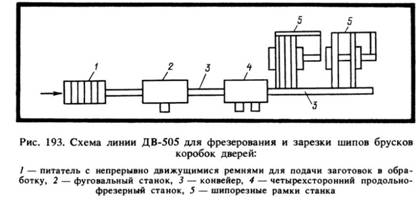
- Sharpening wood cutters: manual work, using grinding wheels and a grinding machine
- Belts and sandriks, crackers and volutes - secret codes of architecture on the example of the old Saratov Sandriks in architecture
- Surface grit - tooling work
- Maximum load on the balcony slab: how much can a balcony withstand in a panel house?
- Projects: symbols on drawings for water supply and sewage
Advertising
| Welding converter 315 500 passport. The device and the scope of the welding converter. Universal welding rectifiers |
|
Depending on the technological process, namely the type of metal being welded and the type of electrode coating for welding, the work is performed either at alternating or at direct current. Direct current from alternating current favorably in that the arc is much more stable. This means that the welding process is easier to lead, and it is possible to carry out the welding process even at small currents. A converter for welding and a transformer are used to stabilize the current. The placement of sources for welding can be individual or centralized. With group placement, equipment is placed at a distance of about 30 - 40 meters from the post, and the power sources themselves are placed at a minimum distance from the welder. The concept of welding converter.The converter for welding is a combination of an electric motor with alternating current and a special welding unit with direct current. In the converter, the electrical energy from the AC network is transferred to the mechanical energy of the device's electric motor, the generator shaft rotates, as a result of which a constant electric current is formed. The efficiency of the converter is not very high, and there are rotating parts in them, as a result of which they are less reliable in their use and not so convenient. However, we note that during construction and installation works, the use of transducers is of higher priority, since they are less sensitive to voltage fluctuations in the network. To supply the welding arc with direct current, both mobile and stationary converters are used.
The welding converter has two parts in itself - a drive electric motor and a welding generator, which are combined under one housing. The transducer anchor and its rotor are located on a common shaft, the bearings of which are attached to the transducer cover housing. Also, a fan is located on the shaft between the electric motor and the generator, which cools the entire system and protects it from overheating. The operation of the transducer is based on electromagnetic induction. Stationary and mobile converters.So, welding transducers can be stationary or mobile. The posts for welding stationary products are located in small welding booths. As a rule, stationary posts are positioned for welding small items. Mobile posts are used for welding fairly large structures: water and oil pipelines, metal structures, etc. At the same time to protect workers from the negative effects of ultraviolet rays propagating from the welding arc, install shields about one and a half meters in height, they are made of non-combustible materials. It is rational to use welding converters for large volumes of welding work. The welding transducer creates a direct current for welding, and the direct current itself is regulated using ballast resistors. Mobile welding posts are usually used during installation and repair work. In this case, the welding converter is installed in trailers or closed cars, they are equipped with knife switches, which are then connected to the equipment. Safety rules when working with converters.When operating the converter, you need to know the following rules for working with these devices:
In conclusion, we can say that the converter is used to transform alternating current into direct current by transferring energy from one state to another. It is necessary to take into account the danger of converters and take the necessary measures to protect workers from the danger of electric shock to workers. A welding electric converter is a combination of a DC generator and a DC electric motor. In the process of work, the conversion of the network AC power into the mechanical energy of the electric motor occurs. As a result of the rotation of the generator shaft, it is converted into direct current electrical energy used for welding. The converter has a relatively small efficiency, and because of the presence of rotating elements in comparison with the rectifier, it is considered less reliable. But for construction and installation work, the use of generators has its advantages. For example, when compared with other sources, they are less sensitive to mains voltage fluctuations. The device of the welding electric converter: electric drive motor, generator, producing welding current. Due to the fact that the design includes rotating elements, the reliability and efficiency of the device is lower than that of standard transformers, rectifiers. But the converters at the same time have their advantage - they produce a welding current that is almost independent of the network voltage drops. It is more expedient to use them in case of increased requirements to the quality of welding works. The working units of the converter of welding equipment, including the control gear, are located in one housing. They are distinguished by mobile units and converters (for carrying out construction and installation works), stationary posts (used in production). They have slightly different characteristics. Principle of operationThe principle of operation of the PSO-500 mechanism provides the ability to produce direct, alternating current. Quite often, in the production workshops, it is the PSO-500 type converters that are used, since they are characterized by high technical performance and reliability. Installation features
SafetyWhen using converters, you must comply with safety requirements for electrical installations:
Despite the fact that welding converters consume more electrical energy due to low efficiency, the presence of mechanical connections, the welding current is always stable regardless of mains voltage drops. This provides the ability to perform high quality welds. It is also necessary to observe the following requirements when working with a welding converter:
In many cases, for the performance of welding work used installation, the main units of which is a step-down transformer, but there are other types of welding equipment. The fact that such a welding transducer, basically only know professionals, but there are many processes in which their use is the only possible option. Constructive deviceA welding transducer is an electrical machine, consisting of a driving electric motor and a generator, which provides the current required to perform the work. Due to the fact that the device of the welding generator includes rotating parts, its efficiency and reliability is slightly lower than that of traditional rectifiers and transformers.
All working units of the welding converter, including the control gear, are mounted in one single housing. At the same time there are mobile welding converters and units, as well as stationary posts. The first, mainly used in the performance of installation and construction works, the second, in the factory. Installations of this type can produce a significant welding current (up to 500 A or more), but it is worth remembering that operation in modes that exceed the standard figure for this parameter is not allowed. Work in critical modes can lead to plant failure. Converter PSO 500The principle of operation of the welding transducer allows to produce direct and alternating welding current. Very often in production you can see the converter PSO 500, which is characterized by high reliability and performance. Its features include the following points:  The PSO 500 welding transducer is mounted on the wheelbase, which provides it with good mobility. Thanks to this, the unit can be operated in a building or installation site. During the operation of welding converters, it is necessary to follow the rules of safe operation of electrical equipment:
Despite the fact that the welding transducer consumes more energy to perform work (due to the presence of mechanical connections and low efficiency), it provides a stable welding current independent of supply voltage fluctuations, which allows improving the quality of the weld. Classification of welding converters and units. For DC welding, power sources are welding transducers and welding units. The welding converter consists of a DC generator and a driving motor, the welding unit consists of a generator and an internal combustion engine. Welding units are used to work in the field and in those cases when the supply voltage varies greatly. The generator and the internal combustion engine (gasoline or diesel) are mounted on a common frame without wheels, on rollers, wheels, in the back of a car and on the basis of a tractor. For work in different conditions, the following units are manufactured: ASB-300-7 - GAZ-320 gasoline engine mounted with a GSO-300-5 generator on a frame without wheels; ASD-3-1 - diesel engine and generator SGP-3-VIII - in the same design; ASDP-500 - like the previous unit, but mounted on a two-axle trailer; SDU-2 - unit mounted on the basis of the tractor T-100M; PAS-400-VIII - engine type ZIL-164. and generator SGP-3-VI, mounted on a rigid frame, equipped with rollers to move on a flat floor. Also other units differing in a design are issued. Welding generators are single-station and multi-station, designed for the simultaneous powering of several welding stations. Single-station welding generators are made with falling or rigid external characteristics. Most of the generators, components of welding units and converters (such as PS and PSO), have a falling external characteristic. The generator converter type PSG has a hard current-voltage characteristic. Universal generators are produced, allowing to obtain both falling and hard characteristics (converters of the PSU type). Welding converters PSO-500, PSO-ZOOA, PSO-120, PSO-800, PS-1000, ASO-2000, PSM-1000-4 and others are supplied mainly with asynchronous three-phase short-circuited motors in one-part design. They have wheels to move around the workshop or are fixed on the stove. Technical data of some converters are given in table. 51. Device and operation of welding generators. The industry produces three types of welding generators: with independent and parallel field windings, demagnetizing series winding and with split poles. Generators with an independent excitation winding and a demagnetizing serial winding (Fig. 119) are used mainly in welding converters PS0420, PSO-ZOOA, PSO-500, PSO-800, PS-1000, ASO-2000, differing in power and design. On the generator diagram (Fig. 199, but) two field windings are shown: independent H and consistent WITHwhich are located at different poles. A resistor is connected to the independent winding circuit. RT. A series winding is made of a bus with a large cross-section, since a large welding current flows in it. From the part of its coils, a tap made on the switch is made P.
The magnetic flux of the series winding is directed towards the magnetic flux created by the independent excitation winding. As a result of the action of these streams, the resulting stream appears. When idling, the serial winding does not work. The no-load voltage of the generator is determined by the current in the field winding. This voltage can be adjusted by a rheostat. RTby changing the magnitude of the current in the magnetizing circuit. When a load is in a series winding, a welding current appears, creating a magnetic flux in the opposite direction. As the welding current increases, the opposing magnetic flux increases, and the operating voltage decreases. Thus a falling external characteristic of the generator is formed (Fig. 119, b). Change the external characteristics by adjusting the current in the winding of the independent excitation and switching the number of turns of the demagnetizing winding. During a short circuit, the current increases so much that the demagnetizing flow increases sharply. The resulting flow, and hence the voltage at the generator terminals, almost drops to zero. The welding current is regulated in two ways: by switching the number of turns of the demagnetizing winding (two ranges) and by a resistor in the independent winding circuit (continuous control). When connecting the welding wire to the left terminal (Fig. 119, but) installed small currents on the right - large. Generators with parallel magnetizing and series demagnetizing excitation windings belong to a system of self-excited generators (Fig. 120). Therefore, their poles are made of ferromagnetic steel having residual magnetism. As can be seen from the diagram (Fig. 120, but), the generator has two windings at the main poles: a magnetizing H and a demagnetizing sequentially connected C. The current of the magnetizing winding is created by the generator anchor itself, for which the third brush serves WITHlocated on the collector in the middle between the main brushes but and b.
The cross-winding inclusion creates a falling external characteristic of the generator (Fig. 120, b). The welding current is smoothly regulated by a resistor RF switched on in the self-excitation winding circuit. For step-by-step current control, the demagnetizing winding is partitioned in the same way as in a PSO generator. According to this scheme, the generators of welding converters PS-300, PSO-ZOOM, PS-3004, PSO-300 PS-500, SAM-400 work. The generator with split poles (Fig. 121) does not have a consistent winding. In this generator, the location of the poles is different from conventional DC electric generators. The magnetic poles do not alternate (the north pole follows the north, then the north again, and so on), and the poles of the same name are located side by side (two north and two south, Fig. 121, b). The horizontal poles Nr are called the main poles, and the vertical N n - transverse.
The main poles have cutouts that reduce their cross-section to fully saturate with magnetic flux already at idle. The transverse poles have a large cross section and operate in all modes with partial saturation. At the main poles are placed only the main excitation windings, and on the transverse - only the transverse. An adjusting rheostat is installed in the transverse winding circuit. RT. Both windings are connected in parallel with each other and receive power from the brushes, i.e. the generator operates with self-excitation. The generator has two main brushes but and b and extra brush with. Under load, a current arises in the armature winding, which creates the armature magnetic flux, which magnetizes the main poles and demagnetizes the transverse. Since the main poles are completely saturated, the effect of the magnetizing flow does not affect. With an increase in the welding current, the magnetic flux of the armature increases, its demagnetizing action (against the flux of the transverse poles) increases and this leads to a decrease in the operating voltage; creates a falling external characteristic of the generator. Thus, the falling characteristic of the generator is obtained by demagnetizing the magnetic flux of the armature. Smooth regulation of the welding current is carried out by a rheostat in the transverse field winding circuit 1. 1 (In previously produced generators of this type (SUG-2a, SUG-26, etc.), the current was roughly adjusted by shifting the brushes from the neutral.) According to the scheme with split poles, the generators of the PS-300M, SUG-2ru converters, etc. work. Design of single-station welding converters. PS-300-1 and PSO-300 converters are used to power one post, for welding, surfacing and cutting. Converters are designed for operating current from 65 to 340 A. The welding generator of the converter refers to the type of generator with parallel magnetizing and series demagnetizing excitation windings. The generator has steeply dipping external characteristics (Fig. 120, b) and two ranges of welding currents: 65 - 200 A and when connecting the welding cable to the left terminal (+) with the full number of turns of the serial demagnetizing winding; 160 - 340 A - when connected to the right terminal (+) with part of the turns of a series winding. In the circuit of the magnetizing field winding included a rheostat of the RU-Zb type with a resistance of 2.98 Ohms for currents of 4.5 - 12 A, designed to regulate the welding current. The PSG-300-1 converter is designed to power the post of semi-automatic welding in shielding gas. The converter generator has a rigid external characteristic, which is created by the magnetizing action of a series excitation winding. The independent field winding is powered by a selenium rectifier connected to an AC network through a ferroresonant stabilizer. A rheostat is connected to the winding circuit of the independent excitation, which allows to smoothly adjust the voltage at the generator terminals from 16 to 40 V. The converter is switched on to the network by means of a packet switch. The limits of regulation of the welding current 75 - 300 A. Universal welding converters PSU-300, PSU-500 have both falling and rigid external characteristics. Converters of this type consist of a single-station welding generator of direct current and a three-phase asynchronous drive motor with a short-circuited rotor located in the same housing. The GSU welding generator is manufactured with four main and two additional poles (Fig. 122). The coils of the main magnetizing field winding, which receives power from the network through a stabilizing transformer and a selenium rectifier, are laid at the two main poles. On the other two main poles are stacked coils of the excitation winding; The magnetic flux of these poles is directed towards the main magnetizing flux. The windings of the additional poles are designed to improve switching.
To obtain steeply dipping external characteristics, an independent excitation winding, a sequential demagnetizing, and part of the windings of the additional poles are turned on. In the transition to a rigid external characteristics (Fig. 122, b) the serial demagnetizing winding is partially disconnected, but an increased number of windings of the additional poles is activated. Changing the appearance of the characteristic is carried out by switching the packet switch installed on the switchgear and connecting the welding wires to the two corresponding terminals on the terminal board. Introduction: Types of welding. Electric welding. Scheme of metal welding arc. Special part: Welding converter. Scheme welding converter PSO-500. The electrical circuit of the welding converter PSO-500. Scheme generator with independent excitation and demagnetizing serial winding. Welding rectifier. The principle of operation of the welding rectifier. The concept of the device svarochnogotransformator and regulator. Electrical Scheme (a) and the magnetic system (b) of the transformer STN in single-body Turn on, regulate and turn off the welding converter. Exploitation: Safety rules for the operation of welding converters. Safety measures for fire fighting equipment during the operation of transformers. Conclusion Literature. The technological process of obtaining permanent connection through the establishment of interatomic and intermolecular bonds between the welded parts of the product when they are heated (local or general), and / or plastic deformation. Welding is used to join metals and their alloys, thermoplastic in all areas of production and in medicine. When welding, various sources of energy are used: electric arc, electric current, gas flame, laser radiation, electron beam, friction, ultrasound. The development of technologies now makes it possible to weld not only in industrial enterprises, but in field and installation conditions (in the steppes, in the field, in the open sea, etc.), under water, and even in space. The welding process is associated with the risk of fire; electric shock; poisoning by harmful gases; damage to the eyes and other parts of the body with heat, ultraviolet, infrared radiation and splashes of molten metal. Types of weldingFriction welding Friction welding, the formation of a welded joint under such a type of pressure welding occurs when the welded products move relative to each other when pressure is applied to them. Spot welding. Spot welding is one of the types of resistance welding of metals. In spot welding, the parts are heated by electric current at the point of contact and compressed (not in all cases). And the main type of joint is an overlap welded joint; therefore, spot welding has become widespread in the automotive industry, in car repairs, for the manufacture of stamped structures. Contact welding. Resistance welding is one of the thermomechanical classes of welding in which a welded joint is formed as a result of heating of the welded products and subsequent plastic deformation of the joint under the action of compressive force. Laser welding. Laser welding is one of the most technologically advanced welding methods; in terms of power density, it is not inferior to electron beam welding, but it does not require the construction of a vacuum chamber. Laser welding is carried out in the environment of protected gases or in air. Unlike an electric arc and an electron beam, magnetic fields do not affect the laser beam - this provides a more stable formation of the weld. Arc welding.Arc welding - a source of heat for heating and melting a metal in this form of welding is an electric arc that occurs between the metal being welded and the electrode. The heat of the electric affects the edges of the parts to be welded, the electrode metal melts - a weld pool is formed. When metal is hardened in the weld pool, a weld is created. To create an electric arc, special sources of direct or alternating current are used.
Electric welding.In electric arc welding, the heat source is an electric arc. A welding arc is an electrical discharge between two electrodes in a gaseous medium, which is accompanied by the release of a large amount of heat and light. When welding according to the Benardos method, one electrode is coal, the other is the metal being welded. When welding by the Slavyanov method, one electrode is a metal melting rod, the other is a metal to be welded. Electrodes are attached by wires to power sources - a welding machine. Excitation - the ignition of the arc - is made by instant contact of the electrodes and their subsequent dilution. At the moment of short circuit, the current arising in the circuit quickly heats the electrodes in the places of their contact. When one of the electrodes moves away, they melt at the point of contact and the space between them is filled with metal vapors. By the action of an arc, the metal being welded is melted to a particular depth, called the penetration depth. The metal of the electrode melted in an arc is transferred to the base metal bath in the form of droplets of various sizes. With a high temperature of metal vapor, the ionization of the space between the electrodes is so significant that a small voltage between the electrodes (about 50 V) is enough to form an electrical discharge. To maintain a stable discharge - an arc - continuous arc ionization is necessary. This ionization is provided by electrons emitted from the surface of the negative electrode (cathode). Free electrons located on the surface of the negative electrode in random motion at high temperatures under the action of an electric field fly out of the cathode. Moving from the cathode, the electrons collide in the arc gap with the molecules of vapors and gases and break them down into positive and negative ions and electrons. The number of electrons escaping from the cathode increases and the kinetic energy imparted by it increases with increasing voltage on the electrodes. With sufficient voltage across the arc, the mutual bombardment of the cathode with positive ions and the anode with negative ions and electrons converts the kinetic energy of these particles into thermal energy. The release of heat and light energy by the electrodes in the welding arc is uneven. In this regard, the temperature of the anode above the temperature of the cathode. The temperature in the axial part of the arc column reaches 6000 ° C.
Fig.1. Scheme of metal welding arc: 1 - electrode; 2 - weld metal; 3 - base metal; 4 - crater; 5 - penetration depth When current passes through an arc gap (at steady arc), the arc burning voltage (15-35 V) will be lower than the ignition voltage (55-60 V). The magnitude of the arc voltage depends on the thermal state of the arc gap, on the degree of its ionization and, mainly, on the arc length. The shorter the arc, the lower the voltage. The welding arc can be powered with direct and alternating current. The arc fed by alternating current is less stable due to the fact that the current in it at the normal frequency of 50 periods 100 times per second changes its direction, and at these moments with a small ionization of the arc gap, the arc can break. To increase the stability of the arc fed by alternating current, apply ionizing coatings on the electrodes and the imposition of high frequency currents on the arc. When welding by a metal electrode according to the method of N. G. Slavyanov, the melted arc metal of the electrode in the form of droplets passes into a bath of molten base metal, mixes and crystallizes in it after cooling, forming a weld. Slavyanov welding can be performed on direct current with direct and reverse polarity and alternating current. The metal welding arc diagram is shown in fig. one. studfiles.net Welding converter.A welding transducer is a combination of an AC motor and a welding generator of direct current. The electrical energy of the AC network is converted into the mechanical energy of the electric motor, rotates the generator shaft and is converted into electrical energy of a constant welding current. Therefore, the efficiency of the converter is small: due to the presence of rotating parts, they are less reliable and convenient in operation compared to rectifiers. However, for construction and installation work, the use of generators has an advantage over other sources due to their lower sensitivity to mains voltage fluctuations. To supply the electric arc with direct current, mobile and stationary welding transducers are produced. In fig. 11 shows the device of a single-stage welding converter PSO-500, mass-produced by our industry.
Fig.1 Scheme of the welding converter PSO-500 2-electric motor 3-fan 4-coil poles 5-Anchor Poles 6-Collector 7-Toko Pullers 8- Handwheel for current control 9 welding terminals 10-ammeter 11-Packet Switch 12-Koropka start-up and control equipment of the converter
A single-station welding converter consists of two machines: from a driving motor 2 and a welding generator of direct current, located in a common housing 1. Anchor 5 of the generator and the rotor of the electric motor are located on a common shaft, whose bearings are installed in the covers of the converter housing. On the shaft between the electric motor and the generator is a fan 3, designed to cool the unit during its operation. The generator anchor is made up of thin plates of electrical steel with a thickness of up to 1 mm and is provided with longitudinal grooves in which insulated windings of the armature winding are laid. The ends of the armature winding are soldered to the corresponding plates of the collector 6. At the poles of the magnets coils 4 are mounted with windings of insulated wire, which are included in the generator electrical circuit. The generator works on the principle of electromagnetic induction. When the armature 5 rotates, its winding intersects the magnetic lines of force of the magnets, as a result of which an alternating electric current is induced in the armature windings, which is converted into a constant collector 6; from the current collector brushes 7, with a load in the welding circuit, current flows from the collector to the terminals 9. Control starting and control equipment of the converter is mounted on housing 1 in a common box 12. The converter is turned on by the package switch 11. Smooth regulation of the magnitude of the excitation current and regulation of the operating mode of the welding generator are produced by a rheostat in the independent excitation circuit of the handwheel8. Using a jumper that connects an additional clamp to one of the positive leads from a series winding, you can set the welding current for up to 300 and up to 500 A. The generator operating on currents exceeding the upper limits (300 and 500 A) is not recommended, as the machine overheats and the switching system is broken. The magnitude of the welding current is determined by an ammeter 10, the shunt of which is connected to the armature circuit of the generator mounted inside the converter housing. The windings of the generator are made of copper or aluminum. Aluminum tires reinforced with copper plates. To protect against radio interference arising from the operation of the generator, a capacitor filter of two capacitors is used. Before starting the converter to work, it is necessary to check the case grounding; condition of the collector brushes; reliability of contacts in the internal and external circuits; rotate the resistors rotate counterclockwise until it stops; check whether the ends of the welding wires touch each other; install a jumper on the board of clamps corresponding to the required welding current (300 or 500 A). The converter is started by switching on the engine to the network (using the package switch 11). After connecting to the network, it is necessary to check the direction of rotation of the generator (if viewed from the side of the collector, the rotor should rotate counterclockwise) and, if necessary, swap the wires at the point of their connection to the mains.
To clarify the principle of operation of the welding converter, consider the simplified electrical circuit of the PSO-500 converter (Fig. 2). The asynchronous electric motor 1 with a short-circuited rotor has three stator windings connected according to the “star” scheme (380 V). Package switch 2 is used to turn on the electric motor in a three-phase AC network of 380 volts. The four-pole welding generator 8 has a winding 5 of independent excitation and a sequential demagnetizing winding 7 providing a falling external characteristic of the generator. Winding 5 and 7 are located at different poles. The independent excitation winding 5 is powered by a direct current from the selenium rectifier 4, which is connected to the power supply of the motor windings through a voltage stabilizer (single-phase transformer) 3 and is turned on simultaneously with the start of the electric motor. The welding current is regulated by a rheostat 6 connected to an independent field winding 5. The current is measured by an ammeter 9. The welding circuit is connected to the terminals of the board 10, which has a jumper that switches the sections of the serial winding 7 to two welding current ranges: up to 300 a and up to 500 but. The capacitors 11 eliminate the interference arising from the operation of the Converter.
(Fig.2) Electrical circuit diagram of welding converter PSO-500 1- Asynchronous motor 2- Batch switch 3- Voltage stabilizer 4- Selenium rectifier 5-winding independent excitation 6- Adjustable rheostat 7- Serial demagnetizing winding 8- Four pole welding generator 9-ammeter 10- board clips 11- Capacitors
The electrical circuit of the welding generator with independent excitation and demagnetizing sequential winding. Figure 3 shows the scheme of the generator GSO-500 with independent excitation and demagnetizing serial winding. The magnetizing winding of the independent excitation is powered by a current from a separate source (AC mains through a semiconductor selenium rectifier), and the demagnetizing is connected in series with the armature winding so that the magnetic flux Fr generated by it is directed opposite to the magnetic flux Fnv of the excitation winding. The current Inv in the excitation winding, and hence the magnitude of the magnetic flux Fnv in it, can be smoothly changed using a rheostat R. A sequential demagnetizing winding is usually sectioned, which allows the use of stepped control of the welding current by changing the number of active ampere turns in the winding. The no-load voltage of the generator is determined by the current in the winding of the independent excitation. With an increase in the welding current Ib, the magnetic flux Fd in the demagnetizing winding increases, which, acting opposite to the Fnv flow of the independent excitation winding, reduces the voltage in the welding circuit, creating a falling external characteristic of the generator (Fig. 146). Change the external characteristics by adjusting the current in the winding of the independent excitation and switching the number of turns of the demagnetizing winding. According to this scheme, welding generators of PSO-120, PSO-800 converters work. To obtain a rigid external characteristic, successive demagnetizing windings are switched so that they act in concert with the winding of independent excitation. According to this scheme, the generators of PSG-350 and PSG-500 converters work.
(Fig.3) Generator circuit with independent excitation and demagnetizing series winding. studfiles.net We study the welding converterA welding electric converter is a combination of a DC generator and a DC electric motor. In the process of work, the conversion of the network AC power into the mechanical energy of the electric motor occurs. As a result of the rotation of the generator shaft, it is converted into direct current electrical energy used for welding. The converter has a relatively small efficiency, and because of the presence of rotating elements in comparison with the rectifier, it is considered less reliable. But for construction and installation work, the use of generators has its advantages. For example, when compared with other sources, they are less sensitive to mains voltage fluctuations. DeviceThe device of the welding electric converter: electric drive motor, generator, producing welding current. Due to the fact that the design of the generator for welding includes rotating elements, the reliability and efficiency of the device is lower than that of standard transformers, rectifiers. The working units of the converter of welding equipment, including the control gear, are located in one housing. They are distinguished by mobile units and converters (for carrying out construction and installation works), stationary posts (used in production). They have slightly different characteristics. Principle of operationThe principle of operation of the PSO-500 mechanism provides the ability to produce direct, alternating current. Quite often, in the production workshops, it is the PSO-500 type converters that are used, since they are characterized by high technical performance and reliability. Installation Features
The converter welding model PSO-500 is mounted on a wheeled chassis, has a small weight. Due to these characteristics, the installation is quite mobile and can be used on construction sites. SafetyWhen using converters, you must comply with safety requirements for electrical installations:
Despite the fact that welding converters consume more electrical energy due to low efficiency, the presence of mechanical connections, the welding current is always stable regardless of mains voltage drops. This provides the ability to perform high quality welds. It is also necessary to observe the following requirements when working with a welding converter:
Sergey Odintsov electrod.biz Pereosnastka.ruWelding metals Device some welding transducers Converter PSO-500. Designed for single-station manual welding and cutting, as well as mechanized welding under a layer of flux. The converter consists of a welding generator of direct current and a three-phase asynchronous electric motor. Normal operation of the converter is possible only with the direction of rotation indicated by the arrow on the generator board. The generator operates according to an independent excitation circuit with a series demagnetizing winding. It has four main magnetic poles. At the two poles there are coils of an independent excitation winding (namachivaya), made with a large number of turns from a thin wire. At the other two main poles there are coils of a series excitation winding (demagnetizing), made by a small number of turns of a thick wire (bus). To ensure normal switching, the generator has two additional magnetic poles. In the box, mounted on the converter case, an independent field winding power supply, an adjustment rheostat, an ammeter, a packet switch for starting and stopping the converter motor are placed. The power supply of the independent excitation winding consists of a single-phase 220/80 V step-down transformer and a selenium rectifier connected in a single-phase bridge (full-wave) circuit. The converter has two welding current ranges - up to 300 A, up to 500 A. The output terminal board has four clips. To the terminals minus (-) and plus (+) connect the welding wires. The positive terminal is connected by a jumper with a terminal of 300 A or with a terminal of 500 A - this is how two ranges of currents are obtained. Smooth adjustment of current in both limits is carried out by an adjusting rheostat. A similar device has a welding transducer PD-501. The PSO-500, PD-501 converters should not be confused with the PSG-500 converter intended for mechanized welding with consumable electrode in a carbon dioxide environment. All of these converters are made in the same basic package and are similar in appearance to each other. The PSG-500 converter has a rigid external characteristic, therefore its use for manual welding with coated electrodes is impossible. It is very easy to distinguish converters according to the board of the output clamps. The PSG-500 converter has only two output terminals: negative (-) and positive (+). Converter PSO-300. Designed for single-station manual welding and cutting. Normal operation of the converter is possible only with the direction of rotation indicated by the arrow on the generator board. The converter generator operates according to a parallel excitation circuit with a series demagnetizing winding. It has four main magnetic poles. At the two poles are placed coils of the parallel excitation winding (magnetizing), made with a large number of turns from a thin wire. At the other two main poles there are coils of a series excitation winding (demagnetizing), made by a small number of turns of a thick wire (bus). To ensure normal switching, the generator has two additional magnetic poles. Fig. 1. Board output clips of the tamping agent PSO-500 In the box mounted on the converter case there is an adjustment rheostat, an ammeter, a packet switch for starting and stopping the converter motor. The converter has two welding current ranges - up to 180 A, up to 300 A. The clip board has four clips. Step and smooth adjustment of the TSC is carried out similarly to the converter PSO-500. Converter 11D-305. Designed for single-station manual welding and cutting. Normal operation of the converter is possible only with the direction of rotation indicated on the end of the converter. The converter consists of a valve DC generator, a three-phase asynchronous electric motor, and control equipment. The valve generator is a high-frequency inductor generator with a built-in rectifier unit. In the slots of the stator of the inductor generator placed three-phase power winding of the armature. The excitation winding is attached to the generator case and placed between two gear packages of the rotor (inductor) of the generator. The rectifier unit of the generator is assembled from silicon valves on a three-phase bridge circuit. The control gear box contains the control gear: a switch for starting and stopping the motor, a switch for welding current ranges, a power supply for the generator excitation winding (voltage transformer, current transformer, rectifier). The converter has two welding current ranges - up to 150 A, up to 350 A, which are provided by switching the three-phase armature winding of the generator. Smooth adjustment of the current within the ranges is carried out remotely by means of an adjustment resistor connected to the control box. PSM-1000-4 converter. Designed for the simultaneous powering of several manual welding stations, which are connected to the converter in parallel via ballast resistors. Normal operation of the converter is possible only with the direction of rotation indicated on the generator board. The converter generator operates according to the mixed excitation scheme. It has four main magnetic poles. Coils of parallel and series windings of excitation are placed on all poles. The coils of the parallel winding have a large number of turns from a thin wire; coils of a series winding have a small number of turns from a thick wire (bus). To ensure normal switching, the generator has four additional poles. For smooth voltage regulation of the generator, an adjustment rheostat is used that is connected to the parallel winding circuit of the generator. Adjustment of the welding current at each welding station is carried out in steps using a ballast resistor. All stages of the rheostat with the help of knife switches can be interconnected in parallel. With an increase in the number of stages involved, the total resistance of the ballast rheostat decreases, and the welding current increases, and vice versa. Ballast rheostat. Is adjustable ohmic resistance consists of several steps. In the welding circuit, the ballast resistor is connected in series with the arc to cut the wire going to the electrode. Each step of the ballast rheostat is included in the welding circuit using a knife switch located on the front wall of the rheostat. The plate also shows an approximate value of the welding current depending on the number of steps included. The elements of the resistance steps of the rheostat are made of heat-resistant Fekhralev wire of rectangular or circular cross section and perform in the form of a spiral. Ballast resistors are available for rated currents of 200, 315, 500 A. Some brands of ballast resistors are: RB-200, RB-201, RB-300, RB-301, RB-302, RB-500, RB-501. The schematic diagram of the ballast rheostat is shown in Fig. 31. If a current value greater than that for which the resistor is designed is required, then two ballast resistors can be switched in parallel. Converter PSU-500. Structurally made similarly to the converter PSO-500. It is universal. Designed for single-station manual welding and cutting, for mechanized welding under a layer of flux, for mechanized welding in a carbon dioxide environment. The generator of the converter has both falling, and rigid external characteristics. Independent generator excitation with series demagnetizing winding. The generator has four main magnetic poles and two additional. Coils of independent (magnetizing) excitation windings made with a large number of turns of thin wire are placed at the two main poles. At the other two main poles there are coils of a serial (demagnetizing) excitation winding. To obtain a falling external transducer characteristic, an independent (magnetizing) and sequential (demagnetizing) excitation windings are used, as well as part of the windings of additional generator poles. To obtain a rigid external characteristic of the converter, part of the turns of the serial (demagnetizing) excitation windings are turned off, but the full number of turns of the windings of the additional poles is turned on. Switching of external characteristics is carried out by a packet switch and connection of welding cables to two corresponding terminals on the terminal board. |


| Read: |
|---|
Popular:
New
- Open lesson "editing, bending"
- Installation of staircases and platforms: general information
- Repair of pipes of water supply in the apartment Repair of steel pipes
- Markup definition. Planar marking. Types of markup. Questions for self-test
- Pipe bending machines Various variations of pipe bending machine
- Safety during filing
- What should be the sharpening angle of the scriber
- Drawing on preparation of contours of future product
- Modern ways of cutting metal and its defects
- Kerner - so that the drill does not slip off!