Site sections
Editor's Choice:
- Court decision on recovery from the management company of the amount of damage to the gulf of the apartment
- Living room and children in the same room: options for partitions
- Top sofa upholstery rating: customer reviews
- Expansion joints in buildings
- Chaber - what is it and its purpose
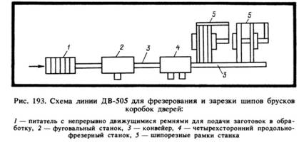
- Sharpening wood cutters: manual work, using grinding wheels and a grinding machine
- Belts and sandriks, crackers and volutes - secret codes of architecture on the example of the old Saratov Sandriks in architecture
- Surface grit - tooling work
- Maximum load on the balcony slab: how much can a balcony withstand in a panel house?
- Projects: symbols on drawings for water supply and sewage
Advertising
| How does the resistance to temperature. The dependence of the resistance of metals on temperature. Let's try to figure out why resistance is increasing. |
|
With increasing conductor temperature, the number of collisions of free electrons with atoms increases. Consequently, the average velocity of the directed motion of electrons decreases, which corresponds to an increase in the resistance of the conductor. On the other hand, as the temperature rises, the number of free electrons and ions per unit volume of the conductor increases, which leads to a decrease in the resistance of the conductor. Depending on the predominance of one or another factor, as the temperature rises, the resistance either increases (metals), or decreases (coal, electrolytes), or remains almost unchanged (metal alloys, such as mangain). With minor temperature changes (0-100 ° C), the relative increment of resistance corresponding to heating by 1 ° C, called the temperature coefficient of resistance a, for most metals remains constant. Having designated - resistance at temperatures, we can write an expression of the relative increment of resistance with increasing temperature from to:
The values of the temperature coefficient of resistance for various materials are given in Table. 2-2. From the expression (2-18) it follows that
The resulting formula (2-20) makes it possible to determine the temperature of the wire (winding), if you measure its resistance at given or known values. Example 2-3. Determine the resistance of the air conductor wires at temperatures if the length of the line is 400 m, and the cross section of the copper wires Line resistance at temperature The resistivity, and hence the resistance of metals, depends on temperature, increasing with its growth. The temperature dependence of the resistance of the conductor is due to the fact that
Experience shows that at not too high and not too low temperatures, the dependences of the resistivity and resistance of the conductor on temperature are expressed by the formulas: \\ (~ \\ rho_t = \\ rho_0 (1 + \\ alpha t), \\) \\ (~ R_t = R_0 (1 + \\ alpha t), \\) where ρ 0 , ρ t is the specific resistance of the conductor substance, respectively, at 0 ° С and t ° C; R 0 , R t is the conductor resistance at 0 ° C and t ° С α - temperature coefficient of resistance: measured in SI in Kelvin minus the first degree (K -1). For metallic conductors, these formulas are applicable starting from a temperature of 140 K and above. Temperature coefficient resistance of a substance characterizes the dependence of the change in resistance upon heating on the type of substance. It is numerically equal to the relative change in resistance (resistivity) of the conductor when heated by 1 K. \\ (~ \\ mathcal h \\ alpha \\ mathcal i = \\ frac (1 \\ cdot \\ Delta \\ rho) (\\ rho \\ Delta T), \\) where \\ (~ \\ mathcal h \\ alpha \\ mathcal i \\) is the average value of the temperature coefficient of resistance in the interval Δ Τ . For all metallic conductors α \u003e 0 and varies slightly with temperature. Pure metals α = 1/273 K -1. Metals have a concentration of free charge carriers (electrons) n = const and increase ρ occurs due to an increase in the scattering intensity of free electrons on the ions of the crystal lattice. For electrolyte solutions α < 0, например, для 10%-ного раствора поваренной соли α = -0.02 K -1. The electrolyte resistance decreases with increasing temperature, since the increase in the number of free ions due to the dissociation of molecules exceeds the growth of ion scattering in collisions with solvent molecules. Dependency formulas ρ and R on temperature for electrolytes are similar to the above formulas for metallic conductors. It should be noted that this linear relationship is preserved only in a small temperature range, in which α = const. For large intervals of temperature variation, the dependence of the resistance of electrolytes on temperature becomes nonlinear. Graphically, the dependences of the resistance of metallic conductors and electrolytes on temperature are shown in Figures 1, a, b. At very low temperatures, close to absolute zero (-273 ° C), the resistance of many metals abruptly drops to zero. This phenomenon is called superconductivity. The metal enters the superconducting state. The dependence of the resistance of metals on temperature is used in resistance thermometers. Usually, platinum wire is taken as the thermometric body of such a thermometer, the dependence of its resistance on temperature has been studied sufficiently. Temperature changes are judged by the change in the resistance of the wire, which can be measured. Such thermometers can measure very low and very high temperatures when conventional liquid thermometers are unsuitable. LiteratureAksenovich L. A. Physics in secondary school: Theory. Tasks. Tests: Textbook. allowance for institutions providing obsch. environments, education / L.A. Aksenovich, N.N.Rakina, K.S. Farino; Ed. K.S. Farino. - Minsk: Adukatsyya i Vyhvanna, 2004. - C. 256-257. In an ideal crystal, the mean free path of electrons is infinite, and the resistance to electric current is zero. This is confirmed by the fact that the resistance of pure annealed metals tends to zero when the temperature approaches absolute zero. The property of an electron to move freely in an ideal crystal lattice has no analogue in classical mechanics. Scattering, leading to the appearance of resistance, occurs in cases where there are structural defects in the lattice. It is known that effective scattering of waves occurs when the size of the scattering centers (defects) exceeds a quarter of the wavelength. In metals, the energy of conduction electrons is 3–15 eV. This energy corresponds to a wavelength of 3 - 7. Therefore, any micro-inhomogeneity of the structure prevents the propagation of electronic waves, causing an increase in the resistivity of the material. In pure metals of perfect structure, the only reason for limiting the electron mean free path is the thermal oscillation of atoms in the lattice sites. The electrical resistance of the metal due to the thermal factor is denoted by ρ warm. It is quite obvious that with increasing temperature, the amplitudes of the thermal oscillations of atoms and the associated fluctuations of the periodic lattice field increase. And this, in turn, enhances the scattering of electrons and causes an increase in resistivity. In order to qualitatively establish the nature of the temperature dependence of the resistivity, we use the following simplified model. The scattering intensity is directly proportional to the cross-section of a spherical volume, which is occupied by an oscillating atom, and the cross-sectional area is proportional to the square of the amplitude of thermal vibrations. The potential energy of an atom deviated by ∆A from the lattice site is determined by the expression
where kpr is the coefficient of elastic coupling, which tends to return the atom to the equilibrium position. According to classical statistics, the average energy of a one-dimensional harmonic oscillator (oscillating atom) is kT. On this basis, we write the following equality:
It is easy to prove that the electron mean free path of N atoms is inversely proportional to temperature:
It should be noted that the resulting ratio is not satisfied at low temperatures. The fact is that with a decrease in temperature, not only the amplitudes of thermal vibrations of atoms, but also the frequencies of oscillations can decrease. Therefore, in the low-temperature region, the scattering of electrons by thermal vibrations of lattice sites becomes ineffective. The interaction of an electron with an oscillating atom only slightly changes the momentum of the electron. In the theory of oscillations of atoms in a lattice, the temperature is estimated with respect to some characteristic temperature, which is called the Debye temperature ΘD. Debye temperature determines the maximum frequency of thermal oscillations that can be excited in a crystal:
This temperature depends on the bonding forces between the lattice sites and is an important parameter of the solid. When T D the resistivity of metals varies linearly with temperature (Figure 6, section III). As the experiment shows, a linear approximation of the temperature dependence т (T) is also valid up to temperatures on the order of (2/3) Dwhere the error does not exceed 10%. For most metals, the Debye characteristic temperature does not exceed 400–450 K. Therefore, the linear approximation is usually valid at temperatures from room temperature and above. In the low-temperature region (T D), where the decrease in specific resistance is caused by the gradual elimination of all new and new frequencies of thermal oscillations (phonons), the theory predicts a power dependence t 5. In physics, this relationship is known as the Bloch-Gruneisen law. The temperature interval in which there is a sharp power dependence t (T) is usually quite small, with the experimental values of the exponent in the range from 4 to 6. In a narrow region I, which is several Kelvin, a number of metals may exhibit a state of superconductivity (more below) and the figure shows a jump in resistivity at a temperature T St. In pure metals of perfect structure, when the temperature tends to OK, the resistivity also tends to 0 (dashed curve), and the mean free path rushes to infinity. Even at ordinary temperatures, the mean free path of electrons in metals is hundreds of times longer than the distance between atoms (Table 2).
Figure 6 - Dependence of the resistivity of a metallic conductor on temperature in a wide temperature range: a, b, c - options for changing the resistivity of various molten metals Table 2 - The average electron mean free path at 0овС for a number of metals Within the transition region II, a rapid increase in the resistivity ρ (T) occurs, where n can be up to 5 and gradually decreases with increasing temperature to 1 at T = D. The linear region (region III) in the temperature dependence of (T) for most metals extends to temperatures close to the melting point. An exception to this rule is ferromagnetic metals, in which additional scattering of electrons takes place on disturbances of the spin order. Near the melting point, i.e. in region IV, the beginning of which is noted in figure 6 with temperature T nl, and in ordinary metals some deviation from the linear dependence can be observed. During the transition from solid to liquid state, most metals exhibit an increase in resistivity of approximately 1.5–2 times, although there are unusual cases: for substances with complex crystal structures like bismuth and gallium, melting is accompanied by a decrease in. The experiment reveals the following pattern: if the melting of the metal is accompanied by an increase in volume, then the resistivity increases abruptly; for metals with the opposite volume change, a decrease in ρ occurs. During melting, there is no significant change in the number of free electrons or in the nature of their interaction. The processes of disorder, a violation of further order in the arrangement of atoms, have a decisive influence on the change in ρ. The anomalies observed in the behavior of some metals (Ga, Bi) can be explained by an increase in the compressibility modulus during the melting of these substances, which should be accompanied by a decrease in the amplitude of thermal vibrations of the atoms. The relative change in resistivity with a temperature change of one kelvin (degree) is called the temperature coefficient of resistivity:
The positive sign of α ρ corresponds to the case when the resistivity in the vicinity of this point increases with increasing temperature. The value of α ρ is also a function of temperature. In the field of linear dependence ρ (T) the following expression is true: where ρ 0 and α ρ are the specific resistance and temperature coefficient of specific resistance, referred to the beginning of the temperature range, i.e. temperature T0; ρ-specific resistance at temperature T. The relationship between temperature coefficients of resistivity and resistance is as follows:
where α 0 is the temperature coefficient of resistance of a given resistor; α 1 - the temperature coefficient of expansion of the material of the resistive element. For pure metals, α ρ \u003e\u003e α 1, therefore, they have α ρ≈ α R. However, for thermostable metal alloys, this approximation turns out to be unfair. 3 Effect of impurities and other structural defects on the resistivity of metals. As noted, the causes of scattering of electron waves in a metal are not only thermal vibrations of lattice sites, but also static structural defects, which also violate the periodicity of the potential field of the crystal. Scattering on static defects of the structure does not depend on temperature. Therefore, as the temperature approaches absolute zero, the resistance of real metals tends to some constant value, called residual resistance (Figure 6). This implies the Mattissen rule on additivity of resistivity:
those. The total resistivity of a metal is the sum of the resistivity due to the scattering of electrons by thermal vibrations of crystal lattice sites, and the residual resistivity due to the scattering of electrons by static structural defects. An exception to this rule is superconducting metals, in which the resistance disappears below a certain critical temperature. The most significant contribution to the residual resistance is made by scattering by impurities, which are always present in a real conductor, either in the form of pollution or in the form of an alloying (i.e., intentionally introduced) element. It should be noted that any impurity additive leads to an increase in , even if it has a higher conductivity compared to the base metal. Thus, an introduction to copper conductor 0.01 at. The proportion of silver impurity causes an increase in the resistivity of copper by 0.002 µm m. It was established experimentally that with a low content of impurities, the resistivity increases in proportion to the concentration of impurity atoms. An illustration of the Mattissen rule is Figure 7, from which it can be seen that the temperature dependences of the specific resistance of pure copper and its alloys with a small amount (up to about 4 at.%) Of indium, antimony, tin, arsenic are mutually parallel.
Figure 7 - Temperature dependences of the resistivity of copper alloys of the type of solid solutions, illustrating the Matissen rule: 1 - pure Cu; 2 - Cu - 1.03 at.% In; 3 - Cu - 1.12 at.% Nl Different impurities affect the residual resistance of metallic conductors in different ways. The efficiency of impurity scattering is determined by the perturbing potential in the lattice, the value of which is the higher, the more strongly the valences of the impurity atoms and the metal - solvent (base) differ. For monovalent metals, the change in residual resistance by 1 at.% Impurity ("impurity" coefficient of electrical resistance) obeys the Linde rule:
where a and b are constants depending on the nature of the metal and the period that an impurity atom occupies in the Periodic System of Elements; Z - the difference between the valences of the metal - the solvent and the impurity atom. From formula 15 it follows that the effect of metalloid impurities on the decrease in conductivity, is stronger than the effect of impurities of metallic elements. In addition to impurities, some contribution to the residual resistance is made by its own structural defects - vacancies, interstitial atoms, dislocations, grain boundaries. The concentration of point defects increases exponentially with temperature and can reach high values near the melting point. In addition, vacancies and interstitial atoms easily arise in the material when it is irradiated with high-energy particles, for example, neutrons from a reactor or ions from an accelerator. The measured resistance value can be used to judge the degree of lattice radiation damage. In the same way, one can trace the recovery (annealing) of the irradiated sample. The change in the residual resistance of copper by 1 at.% Point defects is: in the case of vacancies, 0.010 to 0.015 μOhm Ω; in the case of interstitial atoms, 0.005-0.010 μOhm Ω. Residual resistance is a very sensitive characteristic of chemical purity and structural perfection of metals. In practice, when working with metals of high purity to assess the content of impurities, the ratio of specific resistances at room temperature and liquid helium temperature is measured:
The cleaner the metal, the greater the value of. In the purest metals (degree of purity is 99.99999%), the parameter is of the order of 10 5. Distortions caused by stress state have a great influence on the resistivity of metals and alloys. However, the degree of this influence is determined by the nature of the stresses. For example, with all-round compression for most metals, the resistivity decreases. This is due to the approach of atoms and the decrease in the amplitude of thermal vibrations of the lattice. Plastic deformation and work hardening always increase the resistivity of metals and alloys. However, this increase even with a significant work hardening of pure metals amounts to a few percent. Thermal hardening leads to an increase in , which is associated with lattice distortions, the appearance of internal stresses. During recrystallization by heat treatment (annealing), the resistivity can be reduced to the initial value, since the defects are healed and the internal stresses are removed. The specificity of solid solutions is that the core can substantially (many times) exceed the thermal component. For many two-component alloys, the change in OST depending on the composition is well described by the parabolic dependence of the type where C is a constant depending on the nature of the alloy; x a and x in - atomic fractions of the components in the alloy. Value 16 is called the law of Nordheim. It follows from it that in binary solid solutions A – B the residual resistance increases both when atoms B are added to metal A (solid solution ) and when atoms A are added to metal B (solid solution причем), and this change is characterized by a symmetrical curve . In a continuous series of solid solutions, the resistivity is greater, the further in its composition the alloy is separated from the pure components. The residual resistance reaches its maximum value at equal content of each component (x a = x в = 0.5). The Nordheim law describes quite accurately the change in the resistivity of continuous solid solutions if no phase transitions are observed with a change in composition and none of their components belong to the number of transition or rare-earth elements. An example of such systems can serve as alloys Au - Ag, Cu - Ag, Cu - Au, W - Mo, etc. Solid solutions, whose components are transition metals (Figure 8), behave somewhat differently. In this case, at high concentrations of the components, a substantially large residual resistance is observed, which is associated with the transition of part of the valence electrons to the internal unfilled d - shells of transition metal atoms. In addition, in such alloys, the maximum often corresponds to concentrations other than 50%.
Figure 8 - Dependence of specific resistance (1) and temperature coefficient of specific resistance (2) of copper-nickel alloys on the percentage of components The greater the resistivity of the alloy, the smaller its α ρ. This follows from the fact that in solid solutions the “cond”, as a rule, significantly exceeds t and does not depend on temperature. In accordance with the determination of the temperature coefficient
Considering that α ρ of pure metals is slightly different from each other, expression 17 can be easily converted to the following form:
In concentrated solid solutions, the cave usually exceeds by an order of magnitude or more than ρ t. Therefore, α ρ cfl can be significantly lower than α ρ of pure metal. The production of thermostable conductive materials is based on this. In many cases, the temperature dependence of the resistivity of the alloys turns out to be more complex than that resulting from a simple additive pattern. The temperature coefficient of the resistivity of the alloys can be substantially less than the predicted ratio of 18. The noted anomalies are clearly manifested in copper-nickel alloys (Figure 8). In some alloys, at certain ratios of the components, negative α ρ is observed (in constantan). Such a change in ρ and α ρ from the percentage of alloy components can apparently be explained by the fact that with a more complex composition and structure, as compared to pure metals, the alloys cannot be regarded as classical metals. The change in their conductivity is caused, not only by a change in the free path of free electrons, but, in some cases, by a partial increase in the concentration of charge carriers, with increasing temperature. An alloy in which a decrease in the mean free path with increasing temperature is compensated by an increase in the concentration of charge carriers has a zero temperature coefficient of resistivity. In dilute solutions, when one of the components (for example, component B) is characterized by a very low concentration and can be considered as an admixture, in formula 16, without sacrificing accuracy, you can put (1-x в) 1. Then we arrive at a linear relationship between the residual resistance and the concentration of impurity atoms in the metal:
where the constant C characterizes the change in residual resistance OST for 1 at.% impurity. Some alloys tend to form ordered structures if certain proportions in the composition are maintained during their manufacture. The reason for the ordering is a stronger chemical interaction of heterogeneous atoms compared to atoms of the same kind. The ordering of the structure occurs below a certain characteristic temperature T cr, called the critical temperature (or Kurnakov temperature). For example, an alloy containing 50 at. % Cu and 50 at. % Zn ( - brass) has a body-centered cubic structure. At T 360C, the copper and zinc atoms are randomly and statistically distributed over the lattice sites. The cause of the electrical resistance of solids is not the collision of free electrons with lattice atoms, but their scattering on structural defects responsible for the violation of translational symmetry. When ordering a solid solution, the periodicity of the electrostatic field of the atomic composition of the lattice is restored, thereby increasing the electron mean free path and the additional resistance almost completely disappears due to scattering by the microheterogeneity of the alloy. 4 The effect of the thickness of metal films on the specific surface resistance and its temperature coefficient In the manufacture of integrated circuits, metal films are used for inter-element connections, contact pads, capacitor plates, inductive, magnetic and resistive elements. The structure of the films, depending on the conditions of condensation, can vary from amorphous condensate to epitaxial films — structures of a perfect single-crystal layer. In addition, the properties of metal films are associated with size effects. So their electrical conductivity contribution is significant if the film thickness is comparable with l cf. Figure 9 shows typical dependences of the surface resistance of thin films ρ s and its temperature coefficient α ρ s on the film thickness. Since the relationship of structural (length l, width b, film thickness h) and technological () parameters of the thin film resistor (TPR) is set by the equation:
where ρ s = ρ / h is the square resistance (or specific surface resistance), then we take the traditional notation instead of ρ s and ρ instead of ρ s.
Figure 9- The nature of the change and from the film thickness h The growth of metal films is accompanied by four stages: I - formation and growth of metal islands (mechanisms responsible for charge transfer, - thermionic emission and tunneling of electrons located above the Fermi level. The surface resistance of areas of the substrate where there is no metal film decreases with increasing temperature, which causes negative films of small thickness ); II - tangency of the islands between themselves (the moment of change of the sign of y depends on the type of metal, film formation conditions, impurity concentration, state of the substrate surface); III - the formation of a conductive mesh, when the size and number of gaps between the islands are reduced; IV - the formation of a continuous conductive film, when the conductivity and approach the value of massive conductors, but still the specific resistance of the film is greater than that of the bulk sample, due to the high concentration of defects, impurities trapped in the film during deposition. Therefore, the films oxidized along the grain boundaries are electrically discontinuous, although they are physically solid. Contributes to the growth of and the size effect due to a decrease in the electron mean free path when reflected from the sample surface. In the manufacture of thin-film resistors, three groups of materials are used: metals, metal alloys, cermets. 5 Physical nature of superconductivity The phenomenon of superconductivity is explained by quantum theory, occurs when electrons in a metal are attracted to each other. The attraction is possible in a medium containing positively charged ions, the field of which weakens the Coulomb repulsion forces between electrons. Only those electrons that participate in electrical conductivity, ie located near the Fermi level. Electrons with opposite spin are bound in pairs, called Cooper. In the formation of Cooper pairs, decisive role is played by the interaction of electrons with thermal lattice vibrations — phonons, which it can both absorb and generate. One of the electrons interacts with the lattice - excites it and changes its momentum; the other electron, interacting, translates it into a normal state and also changes its momentum. As a result, the state of the lattice does not change, and the electrons exchange quanta of thermal energy — phonons. The exchange phonon interaction causes the forces of attraction between electrons, which exceed the Coulomb repulsion. Phonon exchange occurs continuously. An electron moving through the lattice polarizes it, i.e. attracts the nearest ions to itself; the density of the positive charge increases near the electron trajectory. The second electron is attracted by a region with an excess positive charge, as a result, due to the interaction with the lattice between the electrons, attractive forces (Cooper pair) arise. These pair formations overlap each other in space, decay and re-create, forming an electron condensate, the energy of which due to the internal interaction is less than that of the aggregate of disconnected electrons. An energy gap appears in the energy spectrum of a superconductor - a region of forbidden energy states. The paired electrons are located at the bottom of the energy gap. The size of the energy gap depends on temperature, reaching a maximum at absolute zero and completely disappears at T st. For most superconductors, the energy gap is 10 -4 - 10 -3 eV. Electron scattering occurs on thermal vibrations and on impurities, but with the presence of an energy gap for the transition of electrons from the ground state to the excited state requires a sufficient portion of thermal energy, which is absent at low temperatures; therefore, the paired electrons are not scattered on structural defects. A feature of Cooper pairs is that they cannot change their states independently of each other, the electron waves have the same length and phase, i.e. they can be considered as a single wave that wraps around the defects of the structure. At absolute zero, all electrons are connected in pairs, with an increase, some pairs break and the width of the gap decreases, at T St all pairs are destroyed, the width of the gap vanishes and superconductivity breaks. The transition to the superconducting state occurs in a very narrow temperature range, the heterogeneity of the structure causes the expansion of the range. The most important property of superconductors - the magnetic field does not penetrate into the thickness of the material, the lines of force go around the superconductor (Meissner effect) - due to the fact that a circular undamped current arises in the magnetic field of the superconductor that completely compensates the external field inside the sample. The depth of penetration of the magnetic field is 10 -7 - 10 -8 m - the superconductor is an ideal diamagnetic; ejected from the magnetic field (a permanent magnet can be made to hang over a ring of superconducting material in which non-decaying currents induced by a magnet circulate). The state of superconductivity is violated when the magnetic field strength is greater than H st. By the nature of the transition of the material from the superconducting state to the state of ordinary electrical conductivity under the action of a magnetic field, superconductors of the first and second kind are distinguished. For superconductors of the first kind, this transition occurs abruptly, for superconductors, the transition process is gradual in the range H cj1 - H cor2. In the interval, the material is in a heterogeneous state, in which the normal and superconducting phases coexist, the magnetic field gradually penetrates into the superconductor, zero resistance is maintained until the upper critical intensity. The critical intensity depends on the temperature for type 1 superconductors:
In type 2 superconductors, the intermediate state region expands with decreasing temperature. Superconductivity can be broken by the current passing through the superconductor if it exceeds the critical value I St = 2πHH St (T) - for type 1 superconductors (type 2 is more complex). 26 metals possess superconductivity (mainly of the 1st kind with critical temperatures below 4.2K), 13 elements exhibit superconductivity at high pressures (silicon, germanium, tellurium, antimony). Do not possess copper, gold, silver: low resistance indicates a weak interaction of electrons with the crystal lattice, and in ferro and antiferromagnets; semiconductors are translated by the addition of a large concentration of dopants; in dielectrics with a high dielectric constant (ferroelectrics), Coulomb repulsion forces between electrons are greatly weakened and they can exhibit the property of superconductivity. Intermetallic compounds and alloys belong to type 2 superconductors, however, this division is not absolute (type 1 superconductor can be turned into type 2 superconductor if you create a sufficient concentration of lattice defects in it. Manufacturing of superconducting conductors is associated with technological difficulties (they have brittleness, low thermal conductivity), create a superconductor composition with copper (a bronze method or a solid-phase diffusion method — pressing and drawing; position of thin niobium filaments in a matrix of tin bronze, with heating tin bronze diffuses into the Nb to form a superconducting film stanida niobium). test questions 1 What parameters depend on the electrical conductivity of metals. 2 What statistics describes the energy distribution of electrons in the quantum theory of the conductivity of metals. 3 What determines the Fermi energy (Fermi level) in metals and what it depends on. 4 What is the electrochemical potential of the metal. 5 What determines the free path of electrons in the metal. 6 Formation of alloys. How does the presence of defects on the resistivity of metals. 7 Explain the temperature dependence of the resistivity of the conductors. 8 NSKurnakova Patterns for ρ and TKS in alloys of the type of solid solutions and mechanical mixtures. 9 Application in the technique of conductive materials with different values of electrical resistivity. Requirements for materials depending on the application. 10 The phenomenon of superconductivity. Scopes of super and cryo-conductors 6 Laboratory work №2. Study of the properties of conductive alloys Objective: to study the patterns of change in the electrical properties of two-component alloys, depending on their composition. In the first part of the laboratory work, two groups of alloys with different phase compositions are considered. The first group includes such alloys whose components A and B dissolve unboundedly in each other, gradually replacing each other in the lattice sites, form a continuous series of solid solutions from one pure component of the alloy to the other. Any alloy of this type in the solid state is single-phase, consists of grains of the same solid solution of the same composition. An example of solid solution alloys are copper-nickel, Cu-Ni, germanium-silicon, Ge-Si, and others. The second group includes alloys, whose components practically do not dissolve in each other, each of the components forms its own grain. Solid state alloy is biphasic; such alloys are called mechanical mixtures. Examples of alloys of the type of mechanical mixtures are Cu-Ag copper-silver systems, Sn-Pb tin-lead systems, etc. During the formation of alloys of the type of mechanical mixtures (Figure 10, a), the properties change linearly (additively) and are the average between the values of the properties of the pure components. In the formation of alloys of the type of solid solutions (Figure 10, b), the properties vary in curves with maximum and minimum.
Figure 10 - Patterns of N.S. Kurnakov. The relationship between the phase composition of alloys and its properties The main electrical properties of metals and alloys are: electrical resistivity ρ, µohm; temperature coefficient of resistance TKS, degree -1. Resistivity of a conductor of finite length
The resistivity of conductor materials is small and lies in the range of 0.016-10 μOm.m. The electrical resistivity of various metallic conductors mainly depends on the average mean free path of an electron λ in a given conductor:
where µ = 1 / λ is the electron scattering coefficient. The scattering factors in the directional motion of the electrodes in metals and alloys are positive ions located in the lattice sites. In pure metals with the most regular, undistorted crystal lattice, where the positive ions are regularly arranged in space, the scattering of electrons is small and is determined mainly by the amplitude of oscillations of the ion in the lattice sites; for pure metals ρ≈ A · μ is warm. where µ is warm - electron scattering coefficient on the lattice thermal vibrations. This electron scattering mechanism is called phonon scattering on lattice thermal vibrations. With an increase in temperature T, the amplitude of oscillations of positive ions at lattice sites increases, scattering of electrons moving directionally under the action of the field increases, the mean free path λ decreases, and the resistance increases. The value estimating the growth of material resistance when the temperature changes by one degree is called the temperature coefficient of electrical resistance of the TCS:
where R 1 - the resistance of the sample, measured at a temperature T 1; R 2 - the resistance of the same sample, measured at a temperature T 2. We study two systems of alloys: the Cu-Ni system, where the components of the alloys (copper and nickel) satisfy all the conditions of unlimited solubility in each other in the solid state, so any of the alloys in this system after the end of crystallization will be a single-phase solid solution (Figure 10, a), and the Cu-Ag system, whose components (copper and silver) do not satisfy the conditions of unlimited solubility, their solubility is small even at high temperatures (does not exceed 10%), and at temperatures below 300 0 C is so small that it can be considered s, it is absent, and any alloy consists of a mechanical mixture of copper and silver grains (Figure 10b). Consider the curve ρ for solid solutions. As you add to any of the pure components of the other component of the alloy, the uniformity in the strict arrangement of positive ions of the same grade is observed, which is observed in pure metals at the lattice sites. Consequently, the scattering of electrons in an alloy like a solid solution is always greater than in any of the pure components due to the distortion of the crystal lattice of the pure components or, as they say, due to the increase in the defectiveness of the crystal lattice, since each introduced atom is of a different type compared to the pure component point defect. From this it turns out that for alloys of the solid solution type, one more type of electron scattering is added — scattering by point defects and electrical resistivity.
Since it is customary to estimate all values of ρ at T = 20 0 С, the determining factor for alloys such as solid solutions is scattering on point defects. The greatest violations of the correctness of the crystal lattice are observed in the region of fifty percent concentration of the components, the curve ρ has the maximum value in this region. From relation 20 it can be seen that the temperature coefficient of resistance of TKS is inversely proportional to the resistance R, and therefore the specific resistance ρ; the TKS curve has a min in the region of the fifty percent ratio of the components. In the second part of the laboratory work alloys with high specific resistance are considered. Such materials include alloys that, under normal conditions, have a specific electrical resistance of at least 0.3 µOhm · m. These materials are widely used in the manufacture of various electrical measuring and electric heaters, exemplary resistances, resistors, etc. As a rule, alloys are used to manufacture electrical measuring instruments, model resistances, and rheostats, which are distinguished by high stability of their specific resistance over time and low temperature coefficient of resistance. These materials include manganin, constantan and nichrome. Manganin is a copper-nickel alloy containing on average 2.5 ... 3.5% nickel (with cobalt), 11.5 ... 13.5% manganese, 85.0 ... 89.0% copper . Doping with manganese, as well as conducting a special heat treatment at 400 ° C, allows stabilizing the manganin resistivity in the temperature range from -100 to + 100 ° C. Manganin has a very small value of thermo-EMF in a pair with copper, high stability of resistivity in time, which allows it to be widely used in the manufacture of resistors and electrical measuring instruments of the highest accuracy classes. Constantan contains the same components as manganin, but in different ratios: nickel (with cobalt) 39 ... 41%, manganese 1 ... 2%, copper 56.1 ... 59.1%. Its electrical resistivity does not depend on temperature. Nichromes are iron-based alloys containing, depending on the grade, 15 ... 25% chromium, 55 ... 78% nickel, 1.5% manganese. They are mainly used for the manufacture of electric heating elements, as they have good resistance at high temperatures in air, due to the close values of the temperature coefficients of linear expansion of these alloys and their oxide films. Among the alloys with high resistance, which (except for nichrome) are widely used for the manufacture of various heating elements, it is necessary to note the heat-resistant alloys fehral and chrome. They belong to the system Fe-Cr-Al and contain in their composition 0.7% manganese, 0.6% nickel, 12 ... 15% chromium, 3.5 ... 5.5% aluminum and the rest is iron. These alloys are highly resistant to chemical destruction of the surface under the influence of various gaseous media at high temperatures. 6.1 Procedure for performing laboratory work No. 2a Before you begin, familiarize yourself with the installation diagram presented in Figure 11, and the instruments necessary for carrying out the measurements. The laboratory setup consists of a thermostat, in which the samples under study are located, and a measuring bridge MO-62, which makes it possible to measure the resistance of a sample in real time. For forced cooling of samples (at T\u003e 25 ° C) a fan is installed on the thermostat and there is a damper on the back surface. On the right side of the thermostat is the sample number switch.
Figure 11 - Appearance and measurement scheme of laboratory work 2a Before starting work, set the “N multiplier” switches to the 0.1 or 0.01 position (as indicated in the table), and the five ten-day switches - to the extreme left position counterclockwise and make sure that the thermostat is turned off (the toggle switch on the front panel of the thermostat in the upper position T≤25 ° C), otherwise, open the damper and turn on the fan with the toggle switch located below the indication lamp, moving it to the lower position until the normal temperature is reached, then turn off the fan. 6.1.1. Set the sample number to -1, fixing the temperature at which measurements will be performed using a thermometer installed on the thermostat; transfer the multiplier of the measuring bridge to the 0.01 position, then turn on the network using the toggle switch located on the upper right of the front panel, and the network indicator will light up. Using decade switches, ensure that the galvanometer needle is at 0 by first pressing the measurement button “exactly”. Selection of resistance to begin with the highest decade by successive approximations, multiply the resulting value by the factor and write it in table 3. Repeat the measurements for the next five samples, then transfer the multiplier to position 0.1 and continue the measurements for samples 7-10. 6.1.2 Return the sample number switch to its original position, close the flap on the back of the thermostat, turn on the thermostat (the switch on the front panel is fully down) and heat the samples to 50-70 ° C, then turn off the thermostat, open the flap and produce measurement of resistance of 10 samples is similar to paragraph 6.1.1, recording the corresponding temperature for each measurement. All the data recorded in table 3. The results show the teacher. 6.2 Procedure for performing work 2b Before you begin, familiarize yourself with the installation diagram presented in Figure 12, and the instruments necessary for its implementation. The installation consists of a measurement unit (BI), where the + 12V power supply is located, a temperature measurement unit (BIT), a thermostat, with samples installed in it, fan for forced cooling of samples, indication of operating modes and temperature, switching facilities (switches of sample number, operating mode, switching on the network, turning on the thermostat and forced cooling), as well as an RLC unit, allowing to measure the resistance of all samples in real time, according to the received task .
Figure 12- Appearance and measurement scheme of laboratory work 2b Before switching on the installation to the network, make sure that the power switch of the K1 network, located on the right side of the measuring unit, and the power switch of the RLC meter are in the “Off” position. 6.2.1 Include in the network RLC-meter and unit of measurement (BI). 6.2.2. K2 toggle switch on the BI in the right position (thermostat off), the red LED is off. 6.2.3 BI operation mode The K4 toggle switch is in the lower position. 6.2.4 Toggle switch "multiplier" - 1: 100, 1: 1 (middle position). 6.2.5 Switches P1 and P2 (sample numbers) - to the position R1. 6.2.6 K3 toggle switch (fan on) - OFF (down position). 6.2.7 Switch on the power supply of the BI (the toggle switch K1, located on the right side of the BI, is in the “on” position, the green LED lights up), switch the toggle switch “multiplier” to 1: 100, make sure that the temperature of the samples is within 20 25 ° C having previously turned on the temperature display by briefly pressing a button on the rear panel of the unit, otherwise, raise the thermostat's lid upward using the screw on the BI lid and turn on the fan, cooling the samples to the specified limits. 6.2.8 Turn on the power of the RLC-meter and select the resistance measurement mode on it. 6.2.9 Using the “N sample” switch on the BI, alternately measure the resistance of 10 samples at room temperature (20-25), then return it to its original position, enter the data in Table 3. 6.2.10 Turn on the thermostat in the BI, switch position K2 “ON” (the red LED lights up) and warm up to 50-60 ° С, raise the fan cover on the BI and turn on the fan (K3 - up). 6.2.11 Make measurements of the resistance of 10 samples, similarly to paragraph 6.2.9, while fixing the temperature at which the measurement was made for each sample. Data should be entered in table 3. Switch “N sample” in the initial position, and the multiplier - in the middle position. 6.2.12 Continue heating the thermostat to T = 65 ºС, lowering the fan cover. Turn off the thermostat, the switch K2 on the BI is in the right position (the red LED is off). 6.2.13 Switch the switch K4 “operation mode” to the position 2 to the BI and the multiplier to the position 1: 1, raise the fan cover. 6.2.14 Perform alternately measuring R1, R2, R3, R4 every (5-10) to a temperature (25-30) С and enter the data in table 4. When the temperature reaches (25-30) ℃ set the multiplier switch - in the middle position, then turn off the network in both devices. (Sample 1-copper, sample 2- nickel, sample 3- constantan, sample 4- nichrome). The report should contain: Objective; Brief description of the installation scheme; Working formulas, explanations, examples of calculation; The experimental results are in the form of a table1 (or tables 3 and 4) and two graphs of dependences of ρ and TKS on the composition of the alloys for the systems Cu-Ag and Cu-Ni, and for sections 6.2.13-6.2.16 - the dependence of the resistance (R) on t ℃ for four samples; The conclusions are based on the experimental results and the study of the recommended literature. Table 3 - Study of the dependence of ρ and TKS on the alloy composition
Conductor length L = 2m; section S = 0.053 μm. Table 4 Study of the dependence of sample resistance on temperature
Literature 1 Pasynkov V.V., Sorokin V.S. Materials of electronic engineering: Textbook. - 2nd ed. - M .: Higher. school., 1986. - 367 p. 2 Handbook of electrical materials / Ed. Yu.V. Koritsky, V.V. Pasynkova, B.M. Tareeva. - M .: Energoizdat, 1988. v.3. 3 Materials in instrumentation and automation. Handbook / Ed. Yu.M. Pyatina, - M .: Mashinostroenie, 1982. 4 Bondarenko G.G., Kabanova T.A., Rybalko V.V. Materials Science.- M .: Yurayt Publishing House, 2012. 359 p. ρ · 10 2, TKS · 10 3, µohm · m 1 / hail Ag 100 80 60 40 20 0 Cu 0 20 40 60 80 100 ρ · 10, TKS, µohm · m 1 / hail. Cu 100 80 60 40 20 0 Ni 0 20 40 60 80 100 Schedule for the teacher - Kirshina I.A. - Assoc., Ph.D. The electrical resistance of almost all materials depends on the temperature. The nature of this dependence is different for different materials. In metals with a crystalline structure, the free path of electrons as charge carriers is limited by their collisions with ions located at the sites of the crystal lattice. In collisions, the kinetic energy of the electrons is transferred to the lattice. After each collision, electrons, under the action of electric field forces, pick up speed again and during the following collisions give the acquired energy to the ions of the crystal lattice, increasing their vibrations, which leads to an increase in the temperature of the substance. Thus, electrons can be considered as intermediaries in the conversion of electrical energy into heat. An increase in temperature is accompanied by an increase in the chaotic thermal motion of particles of a substance, which leads to an increase in the number of collisions of electrons with them and hampers the orderly movement of electrons. For most metals, within operating temperatures, the resistivity increases linearly. where
T1i T2 - the initial and final temperature. For conductors of the second kind, an increase in temperature leads to an increase in their ionization; therefore, TKS of this type of conductors is negative. The values of resistivity of substances and their TKS are given in reference books. Usually, the resistivity values are usually given at a temperature of +20 ° C. The conductor resistance is determined by the expression R2 = R1 Task 3 ExampleDetermine the resistance of the copper wire two-wire transmission line at + 20 ° C and +40 ° C, if the wire cross-section S = 120 mm DecisionAccording to reference tables we find the resistivity
Determine the resistance of the wire at T1 = +20 ° C by the formula R = R1 = 0, 0175 The resistance of the wires at a temperature of + 40 ° C we find by the formula (2.1.2) R2 = 2.917 = 3.15 ohms. The taskThe air three-wire line with a length L is made with a wire, the mark of which is given in table 2.1. It is necessary to find the value indicated by the “?” Sign using the given example and selecting the option with the data specified in it in Table 2.1. It should be noted that the problem, in contrast to the example, provides for calculations associated with a single wire line. In the grades of uninsulated wires, the letter indicates the material of the wire (A - aluminum; M - copper), and the number - the cross section of the wire inmm Table 2.1
The study of the material of the topic ends with the work with tests No. 2 (TOE- ETM / PM "and number 3 (TOE - ETM / IM) Conductor particles (molecules, atoms, ions) that are not involved in the formation of current are in thermal motion, and particles that form a current are simultaneously in thermal and in directional movements under the action of an electric field. Due to this, between the particles that form the current, and the particles that are not involved in its formation, there are numerous collisions, in which the first give a part of the current source energy transferred by them to the second. The more collisions, the slower the speed of the orderly movement of the particles forming the current. As can be seen from the formula I = enνS, a decrease in speed leads to a decrease in current. The scalar quantity characterizing the property of the conductor to reduce the amperage is called conductor resistance. From the formula of Ohm's law, resistance The resistance of the conductor depends on its length l, the cross section S and the material, which is characterized by resistivity Under the action of an electric field, particles that form a current between collisions move rapidly, increasing their kinetic energy due to the field energy. When colliding with particles that do not form a current, they transfer a part of their kinetic energy to them. As a result, the internal energy of the conductor increases, which is externally manifested in its heating. Consider whether the resistance of the conductor changes when it is heated.
In the electrical circuit there is a coil of steel wire (string, Fig. 81, a). Having closed the circuit, we will begin to heat the wire. The more we heat it, the less amperage shows. Its decrease is due to the fact that when metals are heated, their resistance increases. So, the resistance of a light bulb hair when it is off is approximately 20 ohmwhile burning it (2900 ° C) - 260 ohm. When a metal is heated, the thermal motion of electrons and the rate of oscillation of ions in the crystal lattice increase, as a result of which the number of collisions of electrons forming a current with ions increases. This causes an increase in conductor resistance *. In metals, nonfree electrons are very strongly bound to ions; therefore, when metals are heated, the number of free electrons remains almost unchanged. * (Based on electronic theory, it is impossible to derive the exact law of the dependence of resistance on temperature. Such a law is established by quantum theory, in which an electron is considered as a particle possessing wave properties, and the movement of a conduction electron through a metal as a process of propagation of electron waves, whose length is determined by the de Broglie relation.) Experiments show that when the temperature of conductors of different substances changes by the same number of degrees, their resistance varies unequally. For example, if the copper conductor had resistance 1 ohmthen after heating on 1 ° C he will have resistance 1,004 ohmand tungsten - 1,005 ohm To characterize the dependence of the resistance of a conductor on its temperature, a quantity is introduced, called the temperature coefficient of resistance. A scalar quantity measured by a change in the resistance of a conductor in 1 ohm, taken at 0 ° C, from a change in its temperature by 1 ° C, is called the temperature coefficient of resistance α. So, for tungsten, this coefficient is equal to 0.005 degrees -1for copper - 0.004 degrees -1. Temperature coefficient of resistance depends on temperature. For metals, it varies little with temperature. With a small temperature range, it is considered constant for this material. We derive a formula that calculates the resistance of the conductor, taking into account its temperature. Assume that R 0 - conductor resistance at 0 ° Cwhen heated on 1 ° C it will increase by αR 0, and when heated on t ° - on αRt ° and becomes R = R 0 + αR 0 t °, or The dependence of the resistance of metals on temperature is taken into account, for example, in the manufacture of spirals for electric heaters, lamps: the length of the spiral wire and the allowable amperage is calculated from their resistance in the heated state. The dependence of the resistance of metals on temperature is used in resistance thermometers, which are used to measure the temperature of heat engines, gas turbines, metal in blast furnaces, etc. This thermometer consists of a thin platinum (nickel, iron) coil wound on a frame made of porcelain and placed in a protective case. Its ends are included in an electrical circuit with an ammeter, the scale of which is graduated in degrees. When the helix is heated, the current in the circuit decreases, causing the ammeter needle to move, which shows the temperature. The inverse of the resistance of this area, the chain is called electrical conduction conductor (electrical conductivity). Conductivity of the conductor The greater the conductivity of the conductor, the lower its resistance and the better it conducts current. Conductivity Unit Name With decreasing temperature resistance of metals decreases. But there are metals and alloys, the resistance of which at a low jump determined for each metal and alloy, decreases abruptly and becomes vanishingly small - almost zero (fig. 81, b). Is coming superconductivity - the conductor has practically no resistance, and once the current excited in it exists for a long time while the conductor is at superconductivity temperature (in one of the experiments the current was observed for more than a year). When a current is passed through the superconductor 1200 a / mm 2 no release of heat was observed. Monovalent metals, which are the best conductors of the current, do not pass into the superconducting state up to the extremely low temperatures at which the experiments were carried out. For example, in these experiments, copper was cooled to 0,0156 ° K, gold - to 0.0204 ° K. If it were possible to obtain alloys with superconductivity at ordinary temperatures, then this would be of great importance for electrical engineering. According to modern concepts, the main cause of superconductivity is the formation of bound electron pairs. At the temperature of superconductivity between free electrons, exchange forces begin to act, causing the electrons to form bound electron pairs. Such an electron gas from bound electron pairs has different properties than ordinary electron gas — it moves in a superconductor without friction about lattice sites. |
||||||||||||||||||||||||||||||||||||||||||||||||||||||||||||||||||||||||||||||||||||||||||||||||||||||||||||||||||||||||||||||||||||||||||||||||||||||||||||||||||||||||||||||||||||||||||||||||||||||||||||||||||||||||||||||||||||||||||||||||||||||||||||||||||||||||||||||||||||||||||||||||||||||||||||||||||||||||
 ,
(9)
,
(9)
 (10)
(10)

 (11)
(11) (13)
(13) ,
(14)
,
(14)
 ,
(15)
,
(15)

 (17)
(17) (18)
(18) ,
, ,
,


 l and cross section S
  expressed by a known addiction
 (19)
(19)
 (20)
(20) (21)
(21)

 ;
;
 .
. and
and  - specific resistances at initial and final temperatures;
 - constant for this metal coefficient, called the temperature coefficient of resistance (TKS);
 (2.1.2)
 and the length of the line is l = 10 km.
 copper at + 20 ° C and temperature coefficient of resistance
  :
: = 0,0175 Ohm mm
  / m;
/ m;  = 0.004 degrees
  .
. , given the length of the forward and reverse wires of the line:
 2 = 2.917 ohms.
 .
.

| Read: |
|---|
Popular:

New
- Open lesson "editing, bending"
- Installation of staircases and platforms: general information
- Repair of pipes of water supply in the apartment Repair of steel pipes
- Markup definition. Planar marking. Types of markup. Questions for self-test
- Pipe bending machines Various variations of pipe bending machine
- Safety during filing
- What should be the sharpening angle of the scriber
- Drawing on preparation of contours of future product
- Modern ways of cutting metal and its defects
- Kerner - so that the drill does not slip off!