Site sections
Editor's Choice:
- Why at home may there be a need for measuring water resistance?
- Alteration of "Khrushchev" dvushki almost treshku
- Paint the wallpaper with your own hands
- Installation options for drywall in the bathroom
- Court decision on recovery from the management company of the amount of damage to the gulf of the apartment
- Living room and children in the same room: options for partitions
- Top sofa upholstery rating: customer reviews
- Expansion joints in buildings
- Chaber - what is it and its purpose
- Sharpening wood cutters: manual work, using grinding wheels and a grinding machine
Advertising
| As indicated gas boiler on the plan of the apartment. Gas network. conventions. General data on working drawings |
|
STATE STANDARD OF THE UNION SSR SYSTEMSA DESIGN DOCUMENT FOR CONSTRUCTION GAS SUPPLY. WORKING DRAWINGS GOST 21.609-83 STANDARDS PUBLISHING HOUSE Moscow STATE STANDARD OF THE UNION SSR This standard establishes the composition and design rules for working drawings of internal gas supply devices * for buildings and structures of all industries and national economy. * Internal gas supply devices are hereinafter referred to as gas supply. 1. GENERAL PROVISIONS1.1. Working drawings of gas supply are performed in accordance with the requirements of this standard and other standards of the design documentation system for construction, as well as the norms of gas supply design. 1.2. The composition of the working drawings of gas supply (the main set of working drawings of the brand FGP) include: general data on the working drawings; drawings (plans, sections and views) of the location of gas pipelines, gas instrumentation and gas equipment **; gas supply schemes; drawings (plans, sections, types and diagrams) of gas installations; sketch drawings of common types of atypical devices and gas supply structures ***. ** Gas instrumentation and gas equipment are hereinafter referred to as equipment. *** Sketch drawings of general types of atypical devices and structures are hereinafter referred to as drawings of general types. To the main set of working drawings of the GSV brand, the specification of the equipment and the list of material requirements in accordance with GOST 21.109-80 are performed.
1.4. The diameter and thickness of the wall of the pipeline indicate the line of the leader. For gas pipelines made of steel water and gas pipes indicate the diameter of the nominal passage and wall thickness. For gas pipelines from steel electrowelded and other pipes indicate the outer diameter and wall thickness. In the case when the alphanumeric designation of a gas pipeline is indicated on the shelf of the leader line, its diameter and wall thickness are indicated under the shelf of the leader line. 1.5. The risers of gas pipelines are designated by the brand consisting of the letter designation “St” and, through a hyphen, the serial number of the riser within the building (structure), for example St-1, St-2. 1.6. Conditional graphic images of valves (shut-off, regulating and safety) and equipment are accepted according to state standards, taking into account the additional images given in.
2. GENERAL DATA ON WORKING DRAWINGS2.1. The general data of the main set of working drawings of the FGP brand in addition to the data provided for by GOST 21.102-79 include: Key indicators for working drawings of the FGP brand
_________ * The characteristic of the gas used is indicated in a note. 3. DRAWINGS OF THE GAS PIPELINE
|

|
1. Scheme of the gas network in a semi-detached house 2. The diameters in the gas network supplying the meters with one apartment with a bathroom on the floor; with two apartments on the floor. 3. Sizes of niches for 1 - 3 gas meters. OKF is a clean floor level. 4. Niche for 1 electric and 1 gas meter. 5. Niche for 1 electric and 1 gas meter. |
 |
|
6. The room of inputs of engineering networks (DIN 18012) with the turning on and locking devices for strong and weak currents, gas, water supply and the sewerage. 7. Section of the premises of utilities engineering networks. 8. Layout of premises utilities utilities. |
The following devices do not require connection to the gas ducts:
1. All types of gas cookers and gas refrigerators.
2. Heaters with a capacity of up to 10 liters in rooms with a volume of at least tenfold gas consumption.
3. Tanks for boiling linen and washing machines with a gas consumption of up to 2.5 m3 / h in rooms with a volume of at least tenfold gas consumption.
4. Gas heaters installed at the exterior walls with exhaust holes in the wall.
In all other cases (water heaters, laundry boilers and larger washing machines, heating stoves, etc.), gas appliances must be connected to gas ducts.
The supplier is obliged to install a fuse on the outlet nozzle, which eliminates the possibility of condensation and the return of exhaust gases. The automatic dimmer valve of the Dirmeyer system with thermal regulation (Fig. 2) protects the premises from cooling through the flue duct and from violation of the thrust when the exhaust duct is mixed (for off-gases from gas and solid-fuel appliances); in addition, this valve reduces noise. The carbon dioxide content in the air of rooms designed for temporary stay of people (bathroom, kitchen, etc.) should not exceed 0.4%; in rooms for a long stay (common rooms and bedrooms) about 0.15%.
Flues
No more than three firing points are allowed to be connected to the standard-section gas duct of 135 x 135 mm in brick walls: do not make gas ducts of more than 200 x200 mm; firing points operating on solid fuel and gas, if possible, do not attach to one gas duct. Ducts should be located in warm places to avoid condensation on the cold walls. On the top of the flue, you must install a wind cap. On flat roofs, ducts should be no less than 50 cm above the parapet (Fig. 3 and 4).
Gas consumption: for taking a shower for 5 minutes with a water heater with a capacity of 5 liters - 0.25 m3; for heating the room for 15 minutes - 0.25 m3.
Liquefied gas (non-toxic gases - propane, butane, etc.) is used for gas supply in remote areas.
Specifications for liquefied gas (TRF 1969):
| Capacity | Mass in the filled state, kg | Diameter, mm | Height mm | Height with valve, mm |
| Small cylinders | 3 | 205 | 320 | 420 |
| 5 | 230 | 400 | 500 | |
| 11 | 300 | 500 | 600 | |
| Large cylinders | 22 | 270 | 1100 | 1200 |
| 33 | 320 | 1200 | 1300 |
Places for installation of cylinders: small cylinders can be installed in any room except sleeping rooms; large cylinders - outside the building in a lockable metal cabinet or in a room with a separate external entrance; 1 kg of liquefied gas (3 m3 of natural gas) gives about 5000kkal.
Liquefied gas costs almost 1/3 more than gas from the city network.
The diameters of pipes with liquefied gas are significantly less than the diameters of gas pipes of the city network due to increased pressure.
Gas network.
Legend of gas equipment
| 1. | Crossing gas lines with open wiring | |
| 2. | Hidden wiring | |
| 3. | Change the diameters of the gas network pipes | |
| 4. | Air duct | |
| 5. | Impulse piping | |
| 6. | Grounding | |
| 7. | Gas hose | |
| 8. | Ceiling lamp with the number of horns | |
| 9. | Stationary wall lamp | |
| 10. | Mobile Wall Light | |
| 11. | Vent pipe | |
| 12. | Gas duct | |
| 13. | Three-burner gas stove | |
| 14. | Gas stove with oven | |
| 15. | Fridge | |
| 16. | Gas heating stove | |
| 17. | Instantaneous water heater | |
| 18. | Capacitive water heater | |
| 19. | Installing the device in the opening with a seal | |
| 20. | Installing the device in the opening with a gap | |
| 21. | Water bag, water tank | |
| 22. | Wall mounted gas heater | |
| 23. | Gas meter |
Explanations to the accepted terminology:
gas appliances are devices that do not require connection to the ducts;
gas firing points called devices that are connected to the ducts;
the instructions “up to the counter” and “behind the counter” correspond to the direction of gas movement in the network.
Gas consumption: for every 1 m3 of air volume in a heated room during the heating season (September - May) with long-term heating (in residential buildings) 18 -25 m3 of gas, with periodic heating (in commercial premises) –10 -15 m3 of gas.
Color pipelines in the drawings: gas pipelines - yellow, cold water pipelines - light blue, hot water pipes - red.
The diameters of the supply pipelines and gas costs for different devices.
| Type of gas appliance | The diameter of the inlet pipeline, mm. | Gas consumption m3. |
| Fridge | 10 | 0,1 |
| Boiler | 15 | 0,5 |
| Oven | 15 | 0,75 |
| Kitchen stove | 20 | 2,5 |
| Small gas stove | 15 | 1 |
| Gas oven medium and large | 20 | 2,5 |
| Boiling tank (capacity up to 100 liters) | 20 | 3,5 |
| Small water heater | 15 | 2,5 |
| Large water heater (column in the bathroom) | 25 | 6 |
| Household washing machine | 15 | 1,5 |
| Shared washing machine | 15 | 3 |
 |
1. Scheme of the gas network in a semi-detached house 2. The diameters in the gas network supplying the meters with one apartment with a bathroom on the floor; with two apartments on the floor. 3. Sizes of niches for 1 - 3 gas meters. OKF - clean floor level. 4. Niche for 1 electric and 1 gas meter. 5. Niche for 1 electric and 1 gas meter. |
 |
6. The room of inputs of engineering networks (DIN 18012) with the turning on and locking devices for strong and weak currents, gas, water supply and the sewerage. 7. Section of the premises of utilities engineering networks. 8. Layout of premises utilities utilities. |
The following devices do not require connection to the gas ducts:
1. All types of gas cookers and gas refrigerators.
2. Heaters with a capacity of up to 10 liters in rooms with a volume of at least tenfold gas consumption.
3. Tanks for boiling linen and washing machines with a gas consumption of up to 2.5 m3 / h in rooms with a volume of at least tenfold gas consumption.
4. Gas heaters installed at the exterior walls with exhaust holes in the wall.
In all other cases (water heaters, laundry boilers and larger washing machines, heating stoves, etc.), gas appliances must be connected to gas ducts.
The supplier is obliged to install a fuse on the outlet nozzle, which eliminates the possibility of condensation and the return of exhaust gases. The automatic dimmer valve of the Dirmeyer system with thermal regulation (Fig. 2) protects the premises from cooling through the flue duct and from violation of the thrust when the exhaust duct is mixed (for off-gases from gas and solid-fuel appliances); in addition, this valve reduces noise. The carbon dioxide content in the air of rooms designed for temporary stay of people (bathroom, kitchen, etc.) should not exceed 0.4%; in rooms for a long stay (common rooms and bedrooms) about 0.15%.
Flues
| Material | Wall thickness, mm |
| Fireproof ceramic tubes (glazed inside) | 25 – 30 |
| Asbotsementny pipes | 7 – 8 |
| Brickwork with waterproof plaster | 140 |
| Pottery or concrete pipes | 20 – 40 |
| Galvanized Sheet Steel Pipe | 0,6 |
No more than three firing points are allowed to be connected to the standard-section gas duct of 135 x 135 mm in brick walls: do not make gas ducts of more than 200 x200 mm; firing points operating on solid fuel and gas, if possible, do not attach to one gas duct. Ducts should be located in warm places to avoid condensation on the cold walls. On the top of the flue, you must install a wind cap. On flat roofs, ducts should be no less than 50 cm above the parapet (Fig. 3 and 4).
Gas consumption: for taking a shower for 5 minutes with a water heater with a capacity of 5 liters - 0.25 m3; for heating the room for 15 minutes - 0.25 m3.
Liquefied gas (non-toxic gases - propane, butane, etc.) is used for gas supply in remote areas.
Specifications for liquefied gas (TRF 1969)
| Capacity | Mass in the filled state, kg | Diameter, mm | Height mm | Height with valve, mm |
| Small cylinders | 3 | 205 | 320 | 420 |
| 5 | 230 | 400 | 500 | |
| 11 | 300 | 500 | 600 | |
| Large cylinders | 22 | 270 | 1100 | 1200 |
| 33 | 320 | 1200 | 1300 |
 |
 |
| 1. Products of gas combustion 2. Fuse and valve on the instrument connection 3. Flue pipe for flat roofs 4. The same, if there is a veranda |
5. The device of the exhaust duct with double walls 6. Plan of the bathroom and kitchen with a water heater in the hallway niche 7. Small compressed gas cylinders can be installed in any room except sleeping areas. 8. Large cylinders are installed outside in a niche or in a separate lockable sheet steel cabinet. |
 |
9. Diagram of a gas network connected to compressed gas cylinders |
Places for installation of cylinders: small cylinders can be installed in any room except sleeping rooms; large cylinders - outside the building in a lockable metal cabinet or in a room with a separate external entrance; 1 kg of liquefied gas (3 m3 of natural gas) gives about 5000kkal.
Liquefied gas costs almost 1/3 more than gas from the city network.
The diameters of pipes with liquefied gas are significantly less than the diameters of gas pipes of the city network due to increased pressure.
Ernst Neufert. Construction Engineering / Ernst Neufert BAUENTWURFSLEHRE
|
1. Scheme of the gas network in a semi-detached house 2. The diameters in the gas network supplying the meters with one apartment with a bathroom on the floor; with two apartments on the floor. 3. Sizes of niches for 1 - 3 gas meters. OKF is a clean floor level. 4. Niche for 1 electric and 1 gas meter. 5. Niche for 1 electric and 1 gas meter. |
 |
|
6. The room of inputs of engineering networks (DIN 18012) with the turning on and locking devices for strong and weak currents, gas, water supply and the sewerage. 7. Section of the premises of utilities engineering networks. 8. Layout of premises utilities utilities. |
The following devices do not require connection to the gas ducts:
1. All types of gas cookers and gas refrigerators.
2. Heaters with a capacity of up to 10 liters in rooms with a volume of at least tenfold gas consumption.
3. Tanks for boiling linen and washing machines with a gas consumption of up to 2.5 m3 / h in rooms with a volume of at least tenfold gas consumption.
4. Gas heaters installed at the exterior walls with exhaust holes in the wall.
In all other cases (water heaters, laundry boilers and larger washing machines, heating stoves, etc.), gas appliances must be connected to gas ducts.
The supplier is obliged to install a fuse on the outlet nozzle, which eliminates the possibility of condensation and the return of exhaust gases. The automatic dimmer valve of the Dirmeyer system with thermal regulation (Fig. 2) protects the premises from cooling through the flue duct and from violation of the thrust when the exhaust duct is mixed (for off-gases from gas and solid-fuel appliances); in addition, this valve reduces noise. The carbon dioxide content in the air of rooms designed for temporary stay of people (bathroom, kitchen, etc.) should not exceed 0.4%; in rooms for a long stay (common rooms and bedrooms) about 0.15%.
Flues
No more than three firing points are allowed to be connected to the standard-section gas duct of 135 x 135 mm in brick walls: do not make gas ducts of more than 200 x200 mm; firing points operating on solid fuel and gas, if possible, do not attach to one gas duct. Ducts should be located in warm places to avoid condensation on the cold walls. On the top of the flue, you must install a wind cap. On flat roofs, ducts should be no less than 50 cm above the parapet (Fig. 3 and 4).
Gas consumption: for taking a shower for 5 minutes with a water heater with a capacity of 5 liters - 0.25 m3; for heating the room for 15 minutes - 0.25 m3.
Liquefied gas (non-toxic gases - propane, butane, etc.) is used for gas supply in remote areas.
Specifications for liquefied gas (TRF 1969):
| Capacity | Mass in the filled state, kg | Diameter, mm | Height mm | Height with valve, mm |
| Small cylinders | 3 | 205 | 320 | 420 |
| 5 | 230 | 400 | 500 | |
| 11 | 300 | 500 | 600 | |
| Large cylinders | 22 | 270 | 1100 | 1200 |
| 33 | 320 | 1200 | 1300 |
Places for installation of cylinders: small cylinders can be installed in any room except sleeping rooms; large cylinders - outside the building in a lockable metal cabinet or in a room with a separate external entrance; 1 kg of liquefied gas (3 m3 of natural gas) gives about 5000kkal.
Liquefied gas costs almost 1/3 more than gas from the city network.
The diameters of pipes with liquefied gas are significantly less than the diameters of gas pipes of the city network due to increased pressure.
|
GAS NETWORKS. SYMBOLS
Symbols of gas equipment. Explanation of accepted terminology. Color pipelines on the drawings. The diameters of the supply pipelines and gas costs for different devices. Gas ducts. Technical conditions for liquefied gas. Device of gas ducts.
| 1. The intersection of the gas network lines with open wiring 2. Recessed wiring 3. Changing the diameters of the gas network pipes 4. Air duct 5. Pulse pipe 6. Grounding 7. Gas hose 8. Ceiling lamp with indication of the number of horns 9. Fixed wall lamp 10. Wall Mobile lamp 11. Venting pipe 12. Flue 13. Gas stove with three burners 14. Gas stove with oven 15. Refrigerator 16. Gas heating stove 17. Flow-through water heater 18. Capacity water heater 19. Install the appliance in the opening with 20. Installation of the device in the opening with a gap of 21. Water bag, water tank 22. Wall mounted gas heater 23. Gas meter |
Explanations to the accepted terminology:
gas appliances named devices that do not require connection to the ducts;
gas firing points called devices that are connected to the ducts;
the instructions “up to the counter” and “behind the counter” correspond to the direction of gas movement in the network.
Gas consumption: for every 1 m3 of air volume in a heated room for the heating season (September - May) with a long fire (in residential buildings) 18 - 25 m3 of gas, with a periodic fire (in commercial premises) - 10 - 15 m3 of gas.
The color of the pipelines in the drawings: gas pipelines - yellow, cold water pipelines - light blue, hot water pipelines - red.
The diameters of the supply pipelines and gas costs for different devices:

1. Scheme of the gas network in a semi-detached house
2. The diameters in the gas network supplying the meters with one apartment with a bathroom on the floor; with two apartments on the floor.
3. Sizes of niches for 1 - 3 gas meters. OKF is a clean floor level.
4. Niche for 1 electric and 1 gas meter.
5. Niche for 1 electric and 1 gas meter.

The following devices do not require connection to the gas ducts:
1. All types of gas cookers and gas refrigerators.
2. Heaters with a capacity of up to 10 liters in rooms with a volume of at least tenfold gas consumption.
3. Tanks for boiling linen and washing machines with a gas consumption of up to 2.5 m3 / h in rooms with a volume of at least tenfold gas consumption.
4. Gas heaters installed at the exterior walls with exhaust holes in the wall.
In all other cases (water heaters, laundry boilers and larger washing machines, heating stoves, etc.), gas appliances must be connected to gas ducts.
The supplier is obliged to install a fuse on the outlet nozzle, which eliminates the possibility of condensation and the return of exhaust gases. The automatic dimmer valve of the Dirmeyer system with thermal regulation (Fig. 2) protects the premises from cooling through the flue duct and from violation of the thrust when the exhaust duct is mixed (for off-gases from gas and solid-fuel appliances); in addition, this valve reduces noise. The carbon dioxide content in the air of rooms designed for temporary stay of people (bathroom, kitchen, etc.) should not exceed 0.4%; in rooms for a long stay (common rooms and bedrooms) about 0.15%.
Flues
No more than three firing points are allowed to be connected to the standard-section gas duct of 135 x 135 mm in brick walls: do not make gas ducts of more than 200 x200 mm; firing points operating on solid fuel and gas, if possible, do not attach to one gas duct. Ducts should be located in warm places to avoid condensation on the cold walls. On the top of the flue, you must install a wind cap. On flat roofs, ducts should be no less than 50 cm above the parapet (Fig. 3 and 4).
Gas consumption: for taking a shower for 5 minutes with a water heater with a capacity of 5 liters - 0.25 m3; for heating the room for 15 minutes - 0.25 m3.
Liquefied gas (non-toxic gases - propane, butane, etc.) is used for gas supply in remote areas.
Specifications for liquefied gas (TRF 1969):
Places for installation of cylinders: small cylinders can be installed in any room except sleeping rooms; large cylinders - outside the building in a lockable metal cabinet or in a room with a separate external entrance; 1 kg of liquefied gas (3 m3 of natural gas) gives about 5000kkal.
Liquefied gas costs almost 1/3 more than gas from the city network.
The diameters of pipes with liquefied gas are significantly less than the diameters of gas pipes of the city network due to increased pressure.


9. Diagram of a gas network connected to compressed gas cylinders
Created on the basis of:
1. STO GAZPROMREGIONGAZ 1.2-2009 "Graphic display of gas distribution facilities and related communications."
2. GOST 2.780-96 “Unified system for design documentation. Symbols conditional graphic. Air conditioning conditioners, hydraulic and pneumatic tanks. "
3. GOST 2.784-96 “Unified system for design documentation. Symbols conditional graphic. Elements of pipelines.
4. GOST 2.787-71 “Unified system for design documentation. Conditional graphic designations in schemes. Elements, devices and devices of the gas chromatograph system ".
5. GOST 21.609-83 “System of project documentation for construction. Gas supply. Internal devices. Working drawings".
6. GOST 21.404-85 “System of project documentation for construction. Automation of technological processes. Designations conventional instruments and automation tools in the schemes ".
7. GOST 21.206-93 "System of project documentation for construction. Symbols of pipelines ".
Popular:
New
- How to rivet a rivet - automatic and manual methods for different materials What rivet rivet steel sheets
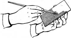
- Appointment of planar marking
- What should be used reinforcing mesh for concrete, wallpaper, plaster technology - plastic, fiberglass or metal
- Edit strip and sheet material
- Open lesson "editing, bending"
- Installation of staircases and platforms: general information
- Repair of pipes of water supply in the apartment Repair of steel pipes
- Markup definition. Planar marking. Types of markup. Questions for self-test
- Pipe bending machines Various variations of pipe bending machine
- Safety during filing