Site sections
Editor's Choice:
- Why at home may there be a need for measuring water resistance?
- Alteration of "Khrushchev" dvushki almost treshku
- Paint the wallpaper with your own hands
- Installation options for drywall in the bathroom
- Court decision on recovery from the management company of the amount of damage to the gulf of the apartment
- Living room and children in the same room: options for partitions
- Top sofa upholstery rating: customer reviews
- Expansion joints in buildings
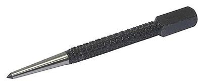
- Chaber - what is it and its purpose
- Sharpening wood cutters: manual work, using grinding wheels and a grinding machine
Advertising
| How to know the thread parameters. Pipe thread sizes. designation. Gosta. Why in inches |
|
The quality of the thread that is cut on the water pipe, as well as its relation to the pipe axis, is extremely important when installing water supply or heating. Manual cutting with a die is not particularly effective - it is much more convenient when the thread is metric and pipe cut with a chisel using a lathe. What is a pipe thread?A thread is called a helical groove with a constant pitch and cross section, which is applied to the surface of machine parts of a weakly conical or cylindrical shape, such as bolts, screws, and also on the surfaces of parts connected to them — for example, nuts. In the home, you have to deal mainly with. Along with metric threads, inch pipe threads are very successfully used in our country. The main characteristics of a metric thread are the pitch (the distance from one depression to another or between the crests of the thread, measured along the detailed axis, which is expressed in millimeters) and the diameter. The main parameters of the inch is the diameter, expressed in inches or parts of an inch, as well as the number of turns cut into an inch. Here it must be recalled that one inch is 25.4 mm. An example for consideration is the cylindrical pipe inch thread of the GOST - most often you have to work with it. There will have to meet with a somewhat unusual unit of measurement - this is the "tube inch", which is equal to 33, 249 mm. It turned out as follows: to the size in inches, which characterizes the internal diameter of the pipe, they added the thickness of both walls. The result was the following result:
The inch thread pipe GOST differs from metric, in addition to the features already described, by the following nuances:
Threads used in everyday lifeIn everyday life, pipes with the following types of threads are most commonly used:
Pipe threadingDetermination of pipe thread pitchTo determine the type, as well as the pitch of the pipe thread, use a tool called thread gauge. You can also use a ruler or a caliper. When determining the pitch of a metric thread, the distance between the vertices of several threads is measured, after which the distance is divided by the number of threads. In the presence of an inch thread, threads are counted, which can fit in one inch (25.4 mm). In practice, of course, it’s hardly possible for someone to ensure such a diameter accuracy, but one can hope to get a completely satisfactory thread, guided by at least one figure that comes after the comma.
Pipe threadingPerformed metric and pipe thread something like this. If this operation is performed manually, and not with a lathe, its implementation is associated with additional difficulties - especially for those with a diameter greater than one inch. The most convenient way is to use a special device for cutting threads manually (KLUP). The device is a body with two handles, where adjustable movable combs are placed, with which the pipe metric thread gradually deepens to the full profile. In addition, you can use interchangeable combs with a full thread profile and an incomplete profile. This tool does not belong to the category of cheap, and since it is not available to everyone, we can mention several devices for ordinary meter (it is also called a die), with the help of which the actual pipe thread is metric. When rotating the ring holder clockwise, it is screwed onto the thread on the sleeve, which, in turn, is fixed on the pipe with three bolts. Such a device has indisputable advantages: there is no “stop” in the pipe at the primary stage of cutting, since pipe and metric threads are easily realized with the sleeve fixed on the pipe.
Metric pipe thread, which is cut by ring holders without extension cords or similar devices, in most cases does not hold up to criticism. They can be equipped with lathe inserts.
The total length of the liners - 100-150 mm. The product itself is a liner with a hole where the stud is inserted - on one side there is an external thread, on the other side there is a tapered section. In other words, on the one hand the insert has a thread, on the other hand - a cylindrical segment, on the lower part of which there are grooves. The diameter of the cylindrical section should be somewhat smaller than the internal diameter of the pipe D, on which the pipe metric thread should be cut. In the walls of this cylinder, three longitudinal slits are made in the lower part (just like at the collet), and if you tighten the pin with a nut inside the insert, the cylinder expands under the influence of the tapered section of the pin and wedges the insert in the pipe. Before starting work, a gauge with a lee-holder is screwed onto the threaded part of the liner, then the liner is inserted into the pipe as far as it will go with the gauge; Thus, fixing (wedging) of the liner in the tube is achieved. The metric pipe thread is cut clockwise by rotating the holder, the gauge is transferred from the thread of the liner to the pipe. Correctly made pipe thread will be the key to success with regard to the tightness of pipe connections, and will serve, during the entire period of operation, directly, the pipes themselves. Federal Education Agency State educational institution higher vocational education "Omsk State Technical University" Threaded productsGuidelines for laboratory work "Threaded parts" for students of full-time and distance learning Compiled by: L.M. Leonova, O.A. Bondarev Guidelines are designed to perform laboratory work and homework in the course “Engineering Graphics” for full-time and distance students in the field 280102 - Safety of production processes and production; 261202 −Technology of printing production. May be useful to students of mechanical and electromechanical specialties. Reprinted by decision of the editorial and publishing council Omsk State Technical University. 1 Preliminary thread informationDefinition, types and purpose of thread Thread is the common name for helical or spiral surfaces of various profiles (triangular, rectangular, trapezoidal, semicircular ...), which are formed on the bodies of revolution by the movement of a flat contour (profile) along a helical line around the body of rotation. Threads are widely used in engineering as a means of connecting, sealing or moving with certain dynamic and kinematic objectives. Actually, the thread is alternating screw protrusions and grooves of the same shape and size. In fig. 1.1 shows the thread on a circular cylindrical rod with triangular turns.
Fig. 1.1 the appearance of the triangular cylindrical thread Purpose (service functions) distinguish threads: mounting metric; mounting and sealing (pipe, tapered); kinematic (trapezoidal or stubborn); special (all non-standard); Depending on the number of screw visits are distinguished threading single pass (one screw surface is cut on the cylindrical surface), and threading multiple pass(two-, three-, four-, etc. start-up) - when the thread is formed by several alternating parallel helical surfaces. These surfaces do not intersect and they are the same in shape and size. In accordance with the shape of the coil profile, threads are called triangular, trapezoidal, circular, etc. (fig. 1.2, 1.3, 1.4, 1.5). In the direction of the turns distinguish the thread rightsand left. Usually used on the details of the right thread.
Fig. 1.4 Trapezoidal threading The thread formed on the surface of the cylinder of rotation is called cylindrical, and on the surface of the cone of rotation, respectively conical carving. If the thread is made on an external surface (for example, a rod), then such a thread is called outdoorand if on the inside (in the hole) - then internal.
but) b) at)
g) d) Fig. 1.5 Types of thread on the rod: but- triangular, b- trapezoidal, at- resistant, g- round, d- rectangular (square) Depending on the pattern of helix formation, the thread may be with constant uniform pitch (it is used most often) or with progressive (increasing or decreasing) pitch. Depending on the system of measures used to measure the geometric elements of the thread, there are inch and metric threads. A thread applied to a flat surface is called a flat thread or spiral. An example of such a thread is the thread on the faceplate of the lathe chuck. It moves the chuck jaws in the radial direction to clamp the part in it. A flat but three-way thread is also cut on the cam shank. Geometric parameters of thread For most of the threads used in mechanical engineering, the standards set the shape and dimensions of the profile, the diameters and pitch of the thread. The nominal dimensions of the thread parameters are common for both the external (threads on the rod) and internal threads (the threads in the holes). The thread parameters include: d 2 (D 2 ) - average thread diameter, which is understood to mean the diameter of an imaginary cylinder coaxially threaded, the generatrix of which intersects the thread profile at points where the groove width is equal to half the nominal thread pitch for a single thread or half the nominal stroke divided by the number of hits for a multiple thread; d (D) - the outer diameter of the thread, which is understood as the diameter of an imaginary cylinder, described with respect to the tops of the external thread or the internal cavity. For most threads, this diameter is taken as nominal; d 1 (D 1 ) - internal diameter of the thread, by which we understand the diameter of an imaginary cylinder inscribed relative to the depressions of the external thread or the tops of the internal; P - the thread pitch, determined by the distance between adjacent like sides of the profile, measured in the direction parallel to the axis of the thread, at a distance equal to half the average diameter from this axis; P h - the thread stroke determined by the value of the relative axial movement of the screw (nut) per revolution. This value is estimated by the distance between the nearest profile sides of the same name that belong to the same screw surface in a direction parallel to the thread axis; α - the angle of the thread profile defined between the lateral sides of the profile in the axial plane; α / 2 - half of the angle of the profile, is determined between the side of the profile and the perpendicular, lowered from the top of the original profile of a symmetrical thread on the axis of the thread; H - the height of the original profile, which is understood as the height of the acute-angular profile obtained by continuing the sides of the profile until they cross (this applies to threads with a triangular profile); H 1 - the working height of the profile, by which is understood the height of the contact of the sides of the profile of the external and internal thread in the direction perpendicular to the axis of the thread; H 2 - profile height determined by the distance between the spring and the depression of the profile in the direction perpendicular to the thread axis; Ψ - the angle of the thread lifting, which is understood as the angle formed by the tangent to the helix at the point lying on the middle diameter and the plane perpendicular to the axis of the thread. The lifting angle is determined by the formula: tgΨ = P/π d 2 ; l - the length of screwing the thread (nut height), which is understood as the length of contact between the screw surfaces of the external and internal threads in the axial direction. These parameters in a standard thread are regulated by the relevant regulatory documents, for example, the profile and parameters of a metric thread are regulated by GOST 8724 - 81 and GOST 24705 - 81 (Fig. 1.6). The basic dimensions of a standard metric thread are shown in table 1.1. External thread always covered, and internal thread in relation to external - always covering. Metric thread is a screw thread on the outer or inner surfaces of products. The shape of the protrusions and hollows that form it is an isosceles triangle. Metric this thread is called because all its geometrical parameters are measured in millimeters. It can be applied on the surface of both cylindrical and conical shape and used for the manufacture of fasteners for various purposes. In addition, depending on the direction of elevation of the turns, the metric-type thread is right or left. In addition to the metric, as is well known, there are other types of thread - inch, pitchevaya, etc. A separate category is modular thread, which is used to manufacture elements of worm gears. Basic parameters and scopeThe most common is metric thread applied to the outer and inner surfaces of a cylindrical shape. That it is most often used in the manufacture of fasteners of various types:
Conical-shaped parts, on the surface of which a metric-type thread is applied, are required in cases where the created joint needs to be given a high tightness. The profile of the metric thread applied to the tapered surfaces allows to form tight joints even without the use of additional sealing elements. That is why it is successfully used in the installation of pipelines through which various media are transported, as well as in the manufacture of plugs for containers containing liquid and gaseous substances. It should be borne in mind that the thread profile of the metric type is the same on cylindrical and on conical surfaces.
Types of threads related to the metric type, distinguished by a number of parameters, which include:
There are additional parameters, depending on which metric threads are divided into different types.
Geometric parametersConsider the geometric parameters that characterize the main elements of the thread of the metric type.
The table of values of diameters of a metric thread (all parameters are specified in millimeters) Values of diameters of a metric thread (mm) Full table of metric threads according to GOST 24705-2004 (all parameters are in millimeters) Full table of metric threads according to GOST 24705-2004 The main parameters of the metric thread type are specified in several regulatory documents.GOST 8724 This standard contains requirements for the parameters of the thread pitch and its diameter. GOST 8724, the current edition of which entered into force in 2004, is the equivalent of the international standard ISO 261-98. The requirements of the latter apply to metric threads with a diameter of 1 to 300 mm. Compared with this document, GOST 8724 is valid for a wider range of diameters (0.25–600 mm). At present, the current edition of GOST 8724 2002, which came into effect in 2004 instead of GOST 8724 81, is relevant. It should be borne in mind that GOST 8724 regulates certain parameters of a metric thread, the requirements for which are stipulated by other thread standards. The convenience of using GOST 8724 2002 (as well as other similar documents) is that all the information in it is contained in the tables, which include metric threads with diameters that are in the above range. The requirements of this standard must meet both the left and right thread metric type. GOST 24705 2004This standard specifies what should be the metric thread of basic dimensions. GOST 24705 2004 applies to all threads, the requirements for which are governed by GOST 8724 2002, as well as GOST 9150 2002. GOST 9150This is a regulatory document, which specifies the requirements for the profile of a metric thread. GOST 9150, in particular, contains data on which geometrical parameters should correspond to the main threaded profile of various sizes. The requirements of GOST 9150, developed in 2002, as well as the two previous standards, apply to metric threads, the turns of which rise from the left upwards (of the right type), and those whose helix rises to the left (of the left type). The provisions of this regulatory document closely overlap with the requirements of GOST 16093 (as well as GOST 24705 and 8724). GOST 16093This standard specifies requirements for tolerances on metric threads. In addition, GOST 16093 dictates how the marking of the thread of a metric type should be carried out. GOST 16093 in the latest edition, which came into effect in 2005, includes the provisions of international standards ISO 965-1 and ISO 965-3. The requirements of such a regulatory document as GOST 16093, includes both left and right thread. The standardized parameters specified in the metric-type thread tables should correspond to the dimensions of the thread in the drawing of the future product. The choice of the tool with which it will be cut should be determined by these parameters. Rules of designationTo denote the tolerance field of a separate diameter of a metric thread, a combination of a digit is used, which indicates the accuracy class of the thread, and the letter defining the main deviation. The thread tolerance area must also be indicated by two alphanumeric elements: in the first place - the tolerance field d2 (average diameter), in the second - the tolerance field d (outer diameter). In that case, if the tolerance fields of the outer and middle diameters coincide, then they are not repeated in the designation.
According to the rules, the first designation is the designation of the thread, followed by the designation of the tolerance field. It should be borne in mind that the thread pitch is not indicated in the marking. You can learn this parameter from special tables. The designation of the thread also indicates to which group it belongs to the length of the screwing. In total there are three such groups:
The letters S and L, if necessary, follow the designation of the tolerance field and are separated from it by a long horizontal line.
Be sure to indicate such an important parameter as the fit of the threaded connection. This fraction is formed as follows: in the numerator is affixed with the designation of the internal thread, referring to the field of its tolerance, and in the denominator - the designation of the tolerance field on the thread of the external type.
Tolerance FieldsThe tolerance fields for the metric threaded element can be of one of three types:
The caliper belongs to the class of universal measuring devices of high accuracy. This device is designed to determine the external and internal dimensions of small parts, the depth of the holes and other parameters. Knowing, you can easily set the linear values of any objects, including threaded connections on the hardware. Features of the use of calipersThe convenience and ease of use of this tool determine its widespread use not only in the manufacturing sector, but also in the home. There are three types of calipers: vernier, dial and digital, differing in their design. The most popular is the first option. Such a tool has a mechanical structure, so there is nothing to break there. With careful handling (it is necessary to protect the device from deformation and rust) its service life is practically unlimited.
Measuring with a caliper as a micrometer, that is, up to tenths of a millimeter, allows the Nonius scale. The design of the tool provides for the possibility of fixing the object being measured both from the outside and from the inside, due to which the probability of error is reduced to zero. Structural elements of devicesTo understand how to measure with calipers, you need to understand its design. The instrument got its name in honor of the bar, on which the main scale is located. An additional scale is a nonius, designed to determine tenths or hundredths of a millimeter if necessary to obtain the most accurate results. The construction of a mechanical vernier caliper consists of:
Some models have a double scale, which allows measuring with a caliper in both millimeters and inches. The remaining structural elements, as a rule, do not have differences. How to measure external surfaces with a caliper
To obtain accurate data on the external dimensional parameters of the object, it must be fixed using the lower jaws of the tool. This operation is performed by preliminarily extending the jaws a little more distance than the size of the measured part, and their subsequent shift against the stop into the surface of the product. After the lower caliper jaws are securely fixed to the outer surfaces, the reference point on the moving scale will take a certain position on the main scale and will show the size of the part.
How to measure the internal diameter of a part with a caliperBefore performing this operation, the elements of the device are shifted to the stop, after which the sponge is placed in the hole to determine the distance between the inner surfaces. Next, they are bred until it stops in the wall and fixed in this position. Knowing how to measure the diameter of a caliper, you can measure the internal planes of any other shape.
Depth determinationThis operation is performed using a depth gauge. The end of the caliper abut in the upper part of the part, and the depth gauge lead into the hole until it stops. The depth of the measured item will be displayed on the main scale. Measurement of threaded connectionsDetermining the size of internal and external surfaces of parts is a simple operation and familiar to many from the school lessons of labor. But not everyone knows how to measure the thread with a caliper.
This procedure may be required in different cases, for example, if the bolt is non-standard or it is necessary to measure the fastener without dismantling the threaded connection. The following are examples of how to measure bolts and nuts with a caliper in various situations.
Taking testimonyFirst of all, it should be noted that the accuracy of the readings depends on the cleanliness of the surfaces of the part, therefore, before measuring with a caliper, it is necessary to remove dirt and grease from the products. Fixing the jaws of the instrument on the part, on the main scale they find a control stroke located on the left in close proximity to the zero vernier stroke. This will be the size of the measured surface in millimeters. Further readings are read in fractions of a millimeter. This operation is performed by finding the division closest to the zero bar and coinciding with the bar on the bar scale. As a result of the addition of its serial number and the price of division of the Vernier, the required indicator is calculated. The most popular models of calipers price division is 0.1 mm. The total value of the instrument readings is obtained by summing up the results in millimeters and in millimeter fractions.
Rules of operation of the caliperIn order for the measuring tool to serve faithfully for many years, it is necessary to follow simple rules for its operation and storage. First of all, avoid mechanical damage that may occur as a result of a fall or force impact. In addition, in the process of measuring parts must not allow the caliper lips to tilt. To prevent this from happening, they need to be fixed in a certain position on the measured part with the help of a locking screw. Store the device only in a soft case or hard case. The second option is preferable, as it can provide protection against accidental deformations. The place to store the caliper should be chosen so as to prevent sawdust from various materials, dust, water, chemical mixtures, etc. Plus, the threat of heavy objects falling onto the instrument should be excluded. After each use of the caliper, it should be thoroughly wiped with a clean, soft cloth. Naturally, we should not forget about the observance of safety rules in the operation of this device. At first glance, it does not pose any threat to health, but this is not entirely true. The fact is that the ends of the sponges for measuring internal dimensions are quite sharp, so you can easily get hurt about them when carelessly handling them. The rest of the tool is completely safe. It would seem that in the pipes of the complex? Connect and cool ... But, if you are not a plumber and not an engineer with specialized education, then questions will surely arise, for answers to which you have to go where your eyes are. And they look most likely the first thing on the Internet) We have already talked about the diameters of metal pipes in this material. Today we will try to clarify the threaded connections of pipes for various purposes. We tried not to overload the article with definitions. Basic terminology contains GOST 11708-82 with which everyone can familiarize themselves. Pipe cylindrical thread. GOST 6357 - 81
Direction: Left Accuracy class: Class A (increased), Class B (normal)
This type of thread is used both in the pipes themselves and in the elements of pipe joints: lock nuts, couplings, elbows, tees ( see picture above). In the section of the profile, we see an isosceles triangle with an angle of 55 degrees and roundings on the tops and valleys of the contour, which are performed for high tightness of the joint. Threaded connections are made on sizes up to 6 ”. All pipes of larger size for reliability of connection and prevent rupture are fixed by welding. Symbol in the international standardInternational: G Japan: PF United Kingdom: BSPP Indicates the letter G and the diameter of the bore (internal Ø) of the pipe in inches. The outer diameter of the thread itself is not present in the designation. Example: G 1/2 - external cylindrical pipe thread, internal pipe Ø 1/2 "". The outer diameter of the pipe will be 20.995 mm, the number of steps on a length of 25.4 mm will be 14. The accuracy class (A, B) and the direction of the coils (LH) can also be indicated. For example: G 1 ½ - B - cylindrical pipe thread, internal Ø 1 ½ ”, accuracy class B. G1 ½ LH- B - cylindrical pipe thread, internal Ø 1 ½ inch, accuracy class B, left. The fastening length is indicated last in mm: G 1 ½ -В-40. For an internal pipe cylindrical thread, only the pipe Ø for which the hole is intended will be indicated. Tube size table
How to determine the pitch of the inch thread
I bring you a picture from the English-language Internet, which clearly demonstrates the technique. Pipe threads are not characterized by the size between the profile tops, but by the number of turns per inch along the thread axis. To help ordinary roulette or ruler. We apply, measure one inch (25.4 mm) and count the number of steps visually. In the picture with an example ( see above) threads - from English it is literally "thread thread." In this case, there are 18 of them. by one inch. It is even easier if the thread gauge for the inch thread was in the box in your tool box. Measurements are very convenient to carry out, but it must be remembered that the thread may vary in the apex angle of 55 ° and 60 °. Tapered pipe threads
drawing pipe tapered threads Conical pipe thread GOST 6211-81 (1st size)Unit of measurement: Inch Corresponds to the rounded profile of a pipe cylindrical thread with an angle of 55 °. Cm. top Part (I) of the three-dimensional image "drawing pipe tapered threads". SymbolInternational: R Japan: PT United Kingdom: BSPT Indicates the letter R and the nominal diameter Dy. The designation R means the external appearance of the thread, Rc internal, Rp internal cylindrical. By analogy with a cylindrical pipe thread for the left-hand thread is used LH. Examples: R1 ½ - external pipe tapered thread, nominal diameter Dy = 1 ½ inch. R1 ½ LH - external pipe tapered thread, nominal diameter Dy = 1 ½ inch, left. Conical inch thread GOST 6111 - 52 (2nd type)Unit of measurement: Inch Has a profile angle of 60 °. Cm. lower Part (II) of the three-dimensional image "drawing pipe tapered threads". It is used in pipelines (fuel, water, air) machines and machines with relatively low pressure. The use of this type of connection implies tightness and thread locking without additional special means (flax, yarn with red lead). SymbolExample: K ½ GOST 6111 - 52 It stands for: conical inch thread with external and internal diameter in the main plane approximately equal to the external and internal Ø of a pipe cylindrical thread G ½ Table of the main parameters of the tapered inch thread
Metric tapered thread. GOST 25229 - 82
Unit of measurement: mm Made on taper surfaces 1:16 Used when connecting pipelines. The angle at the top of the coil is 60 °. The main plane is offset from the end ( see pic above). SymbolFollowing the letters MK is an indication of the diameter in the main plane and the thread pitch in mm: MK 30x2 Size table for metric tapered threads
The characteristic of the cylindrical pipe / inch thread relative to the metricThe main characteristics of "inch" and "pipe" cylindrical threads in relation to the "metric" thread for basic sizes.
|
||||||||||||||||||||||||||||||||||||||||||||||||||||||||||||||||||||||||||||||||||||||||||||||||||||||||||||||||||||||||||||||||||||||||||||||||||||||||||||||||||||||||||||||||||||||||||||||||||||||||||||||||||||||||||||||||||||||||||||||||||||||||||||||||||||||||||||||||||||||||||||||||||||||||||||||||||||||||||||||||||||||||||||||||||||||||||||||||||||||||||||||||||||||||||||||||||||||||||||||||||||||||||||||||||||||||


Popular:
New
- How to rivet a rivet - automatic and manual methods for different materials What rivet rivet steel sheets
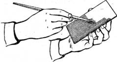
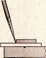
- Appointment of planar marking
- What should be used reinforcing mesh for concrete, wallpaper, plaster technology - plastic, fiberglass or metal
- Edit strip and sheet material
- Open lesson "editing, bending"
- Installation of staircases and platforms: general information
- Repair of pipes of water supply in the apartment Repair of steel pipes
- Markup definition. Planar marking. Types of markup. Questions for self-test
- Pipe bending machines Various variations of pipe bending machine
- Safety during filing