Site sections
Editor's Choice:
- Why at home may there be a need for measuring water resistance?
- Alteration of "Khrushchev" dvushki almost treshku
- Paint the wallpaper with your own hands
- Installation options for drywall in the bathroom
- Court decision on recovery from the management company of the amount of damage to the gulf of the apartment
- Living room and children in the same room: options for partitions
- Top sofa upholstery rating: customer reviews
- Expansion joints in buildings
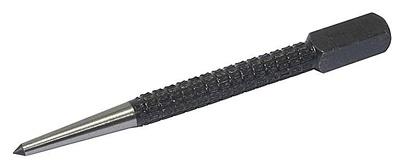
- Chaber - what is it and its purpose
- Sharpening wood cutters: manual work, using grinding wheels and a grinding machine
Advertising
| Size designations on the drawings. Dimensioning rules. Perimeter and area |
|
According to the images of the object on the drawing judge its size and the size of its individual parts. The basis for this are the dimensional numbers, no matter what the scale and with what accuracy Fig. 7
Fig. eight
Fig. 9
Fig. ten
Fig. eleven
Fig. 12
Fig. 13 completed images. Rules for applying dimensions in the drawings are established by GOST 2.307-68. Dimensions in the drawing indicate dimensional numbers, dimension and extension lines. Dimension numbers in drawings, as a rule, indicate in millimeters without specifying the units of measurement. In cases where it is necessary to use other units of length, they are shown after the dimensional number. Dimension numbers are applied above the dimension line, possibly closer to its middle. The gap between the dimension number and the dimension line should be about 1.0 mm. The height of the digits of dimensional numbers is not less than 3.5 mm (Fig. 7). The dimension line is drawn parallel to the segment, the size of which is applied above it. It is carried out between the extension lines drawn perpendicular to the dimension. It is allowed to draw dimension lines directly to the lines of the visible contour, axial and center lines. In some cases, the dimension line may not be perpendicular to the extension (Fig. 8). Dimension lines limit the arrows (Fig. 9). In some cases, they are not carried out completely, but with a broken arrow on one side (Fig. 10). The size of the arrow is chosen from the thickness of the solid thick base line adopted in the drawing. Within the limits of one drawing the size of arrows should be whenever possible identical. It is not recommended to use contour, axial, center and extension lines as dimension lines. If the length of the dimension line is small to accommodate the arrows, then the dimension line is continued beyond the extension lines, and the dimensions are applied, as shown in Fig. eleven. Extension lines are drawn from the boundaries of the measurements, they are auxiliary and are used to place the dimension lines between them. Extension lines should, if possible, be located outside the image contour, perpendicular to the straight line segment, the size of which must be specified. Extension lines should extend beyond the ends of the dimension line arrows by 1 ... 5 mm (Fig. 12). The minimum distance from the dimension line to the line parallel to it should be 10 mm, and between the parallel dimension lines - 7 mm. Angular dimensions in the drawings are put in degrees, minutes and seconds, indicating the units of measurement. The size of the angle is applied above the dimension line, which is held in the form of an arc with its center at its top. Extension lines in this case are drawn radially (Fig. 13). At different inclinations of dimension lines, dimensional numbers of linear dimensions are arranged as shown in Fig. 14, a, and angular dimensions - as shown in fig. 14, b.If the dimension line is in the zone that is shaded in the drawing, the dimensional numbers are applied on the shelves of the callout lines (Fig. 15). If there is not enough space for writing a dimension number above the dimension line, or is this space occupied by other elements of the image and
Fig. 14
Fig. 15
Fig. sixteen
Fig. 17 it is impossible to put a dimension number into it; a dimension number is applied in one of the options shown in fig. sixteen. In order to simplify a number of images, create convenience for reading the drawing, the standard provides for the use of symbols in the form of letters of the Latin alphabet and graphic signs, which are placed before the dimensional numbers. In the drawings apply
Fig. 18
Fig. nineteen
Fig. 20
Fig. 21
Fig. 22
Fig. 23
Fig. 24 signs and letters to denote the diameter and radius, the length of the arc and the square, the slope and taper, the sphere, the thickness and length of the part. Before the size number of the diameter, the sign 0 is applied (fig. 17). Moreover, there is no gap between the sign and the number. For circles of small diameter, the dimension lines of the arrow and the size itself are applied in one of the options shown in fig. 18. Before the size number of the radius of the arc is always put a sign in the form of a capital Latin letter R.The dimension line in this case is carried out towards the center of the arc and is limited to only one arrow, which runs into the arc or its continuation (Fig. 19). If the radius on the drawing is less than 6 mm, the arrow is recommended to
Fig. 25 lay on the outside of the arc. If it is necessary to set the position of the center of the arc, it is marked by the intersection of the center or extension lines (Fig. 20). In cases where the drawing shows an arc of a large radius, for which the center can not be indicated, the dimension line is cut off, not reaching the center (Fig. 21). If in this case the center should be noted, it is allowed to bring it closer to the arc (Fig. 22). The dimension line in this case is shown with a break of 90 °, and both sections of the dimension line are held in parallel. You should not place on one straight dimension lines that extend from one center and are intended to indicate dimensional arcs. Radiating is recommended to designate arcs up to 180 °; arcs whose magnitude is greater than 180 ° are denoted by diameter. The arc sign is applied above the dimension number (fig. 23). The length of the arc is given in linear units, and the dimension number indicating the arc is drawn over the dimension line in accordance with the usual requirements. For setting the dimensions of the square, the corresponding sign D is used, whose height is equal to 7/10 of the height of the dimension number (Fig. 24, but).If the square is otherwise located, the dimensions of its sides are applied (Fig. 24, b).It should be noted that the sign of the square is applied only on the image in which it is projected in a line. The sign of the surface taper is applied on the shelf of the leader line parallel to the axis of the cone or on the axis of the cone (Fig. 25, but).The taper sign is positioned so that its acute angle is directed toward the apex of the cone. The value of the taper is determined by the ratio of the difference of the diameters of the two cross sections of the cone to the distance between these sections, i.e. k= D- dll,where D- diameter of a large section; d- diameter of smaller section; / - the distance between sections. The taper is indicated as a simple fractional number (Fig. 25, b). The sign of the slope of a straight line indicate the shelf line-callouts. Bias i is the tangent of the angle between a given straight line and a horizontal or vertical straight line (Fig. 26, a). Slope sign is located
Fig. 26
Fig. 27
Fig. 28 so that its acute angle is directed towards the slope of a straight line (Fig. 26, b).The slope, like taper, in the drawing is set with a simple fraction, as a percentage or in ppm. To designate a sphere in the drawing, use the sign of diameter or radius. In cases where the sphere is difficult to distinguish from other surfaces from a drawing, the word “Sphere” may be added before the sign of the radius or diameter. The inscription on the drawing is carried out as "Sphere diameter 17" or "Sphere R10 "(Fig. 27). Simple flat parts are depicted as a single projection. In these cases, its thickness is denoted by a lowercase letter. sand the inscription on the drawing is performed by type s2and is located on the shelf of the callout line (Fig. 28, a). The length of the subject indicate the letter / (Fig. 28, b). Chamfers in the drawings are applied in two linear dimensions (Fig. 29, but)or one linear and one angular (Fig. 29, b).In case if
Fig. 29 the angle of inclination of the generatrix of the cone is 45 °; simplified chamfering is used when the dimension line is drawn parallel to the axis of the cone, and the inscription is of the type “2 x 45” (Fig. 29, c). QUESTIONS FOR SELF-TESTS 1. What are the classification groups of standards ESKD? 2. How many A4 sheets are in A1 format? 3. What are the rules for the location of the main inscription on the format? 5. What scale do you know? 6. How are the scales indicated? 7. What is the thickness of axial, center, extension and dimension lines? 8. What lines are used to stroke the contour? 9. What determines the font size? 10. How is the height of lower case letters determined? 11. What marks are used when applying dimensions? 12. At what distance from each other and from the contour line draw dimensional lines? 13. When put a sign of diameter 0, and when the sign of the radius R? 14. Where do they put on the drawing the size of the number relative to the dimension line? 15. How does the image scale affect the size of the dimensions on the drawing? 16. What is bias, as it is designated in the drawing? 17. What is the taper, as it is denoted in the drawing? 18. How do conic chamfers in the drawing Part Three All images are accompanied by the application of sizes. When applying dimensions should be guided by the main provisions of GOST 2.307-2011 "Drawing dimensions and maximum deviations." The basis for determining the size of the depicted product and its elements are the dimensional numbers indicated in the graphic document. The numerical value of the size to be supplied must correspond to its natural value (actual value), regardless of the accepted scale of the image. In the training drawings, only nominal dimensions are plotted without indicating their maximum deviations. Linear dimensions are indicated on the drawing in millimeters with no indication of the unit of measurement, angular dimensions are in degrees, minutes. Dimensions in graphic documents are indicated by dimension numbers and dimension lines. When drawing the size of a straight line segment, the dimension line is drawn parallel to this line, the extension lines are perpendicular to the dimension line (figure 7). Fig. 7. Rules for dimensioning in the drawing Dimension lines are preferably applied outside the contour of the image. It is not allowed to use contour lines, axial, center and extension lines as dimension lines. It is necessary to avoid the intersection of dimension and extension lines. A dimension line at both ends is limited by arrows that rest against extension lines. The shape of the arrow and the approximate size ratio of its elements are shown in Fig. eight.
Fig. 8. The image of the arrows on the drawing Extension lines are drawn from the lines of the visible contour. Extension lines should extend beyond the ends of the dimension line arrows by 1 ... 5 mm. The distance between the contour line and the dimension line is selected depending on the image size and saturation of the drawing. The minimum distance between the dimension line and the contour line should be 10 mm, and the minimum distance between parallel dimension lines should be 7 mm. Dimension numbers are applied over the dimension line as close as possible to its middle. When drawing several parallel dimension lines, dimension numbers should be arranged in a checkerboard pattern (Fig. 7). If there is not enough space for the application of arrows and dimension numbers, they are applied using one of the methods shown in fig. 9. With a lack of space for the arrows on the dimension lines arranged in a chain, the arrows may be replaced with serifs of 1-3mm length, plotted at an angle of 45 ° to the dimension lines or clearly plotted points (Fig. 9). If there is not enough space for an arrow due to a closely located contour or extension line, the latter can be interrupted.
Fig. 9. Dimension lines Dimension numbers are not allowed to be divided or intersected by any lines of the drawing. In the place where the dimension number is applied, the axial, center lines and lines of the hatching interrupt (Fig. 10).
It is recommended to group the dimensions related to the same structural element (groove, protrusion, hole, etc.) in one place, placing them on the image in which the geometric shape of this element is shown most fully (Fig. 11).
Fig. 11. Group sizes When drawing the size of the arcs indicate its radius for the circle - the diameter. A capital Latin letter “ R» , (eg, R20 ), before the size number of the diameter - the sign "« "(for example, 20 ). In the case of an image of a part with a spherical surface, if it is difficult to distinguish it from other surfaces, it is allowed to apply the word “Sphere” or the “” sign when applying the diameter (radius) dimension (for example, SphereR15 or 40 ). The square in the drawing is determined by two sizes of its sides or one size with a “” sign (Fig. 12). Diagonals on the face of the element, drawn in thin lines, conventionally denote a plane. The dimensions of the chamfers at an angle of 45º are applied as shown in Figure 12. but. The width of the chamfer and the angle are combined in one size using the “×” sign. The dimensions of the chamfers at different angles indicate separately linear and angular dimensions (in Figure 12 butthe dimensions of the chamfer are indicated at an angle of 30º with a chamfer width of 3mm) or two linear dimensions (Fig. 12 b).
Fig. 12 but Fig. 12 b If a view or section of a symmetrical object or separate symmetrically arranged elements is depicted only up to the axis of symmetry or with a break, then the dimension lines relating to these elements are drawn with a break, and the break of the dimension line is made further than the axis or break line of the object (Fig. 13).
Fig. 13. Dimensioning with breakage The total number of sizes should be minimal, but sufficient to manufacture and control the product. The dimensions of the same element in the drawing are not allowed to be repeated. Dimensions of several identical elements of the product, as a rule, are applied once with the number of these elements on the shelf or below it (Fig. 14). Moreover, for elements evenly spaced around the circumference (for example, holes), the angular dimensions between them are not set, provided that one of these elements lies on one of the axes of symmetry (Fig. 14 but). Only the size of the diameter of the circle on which the centers of the holes in fig. 14 but. If none of the holes lies on the axis of symmetry, then you should set the angle to the first element (Fig. 14 b).
Fig. 14 but Fig. 14 b - It is a quadrangular rectangle, which is a figure with equal angles and sides, between themselves. The word " square"Comes from the Greek word" quadratus", Which means -" quadrangular». In technical drawings it is not uncommon to see parts or parts of them having a square cross section. To reduce the total number of dimension lines in the drawing, in this case, the special sign “” is used, which means that this size is one of the sides of the square, and the size is indicated only here. The height of the sign is selected according to the height of the dimensional numbers. Designation of the square section of the product Parts areas, having a square cross-section can often be found on the fastening elements of the auxiliary and cutting tool. Installation boltsused in this case, take on significant mechanical stress at intervals due to technological process. Machine visedesigned for installation on machine tools, equipped with a power screw, at one end of which there is a square section. This was done so that the cap knob, which respectively has a hole with a square cross-section, could be freely removed and put on, while it becomes possible to change its angular position. The load applied to the mechanisms of the vice, is also very significant. As is well known, a significant part of the parts of rotation is made on lathes of the group. In order to clamp the part or workpiece for subsequent machining using special self-centering cartridges. The most common of these are three cam lobes, but there are also four cam cartridges in which, by the way, you can clamp square parts or blanks from the corresponding rolled products. The square can also be clamped in two cam cartridges, while, like in four cam cartridges, the cams can be moved, depending on the type, independently or using a special mechanism based on " Archimedean spiral"That allows you to move the clamping elements synchronously. There are even six cam cartridges, all of which are united by the fact that a square head wrench is used to clamp the part. In the construction of a traditional type tap mixer, a water supply control element, such as a stem, is included. At one end of the stem there is a square cross-section, on which a handle with a square hole is installed. Efforts here are not to say that it is too big but, nevertheless, the use of a hexagon is not appropriate here (during operation, the angles between the faces may simply collapse). Square holes, in contrast to round holes, are the most laborious to manufacture. Usually they are milled, drawn, special firmware is used, dispersed on a slotting machine, etc. Technologies like - laser cutting or eDM treatment, allow more or less quickly expose the processing of hollow elements of this type. There is, however, another, exotic way. We are talking about drilling, using a special tool. This method is based on the trajectory of movement " relo triangle”, Named after the German inventor - mechanical engineer Franz Relot, who lived in the nineteenth and early twentieth centuries, for a long time was a lecturer at the Berlin Royal Technical Academy and eventually became its president. In the cross section of the drill like the so-called " relo triangle», The sides of which are not straight segments, as in the ordinary, but arcs of the same size and radius. If in the process of drilling with the help of a special tool to move the axis of this tool along a special trajectory, then you end up with a square hole with slightly rounded corners. In cases where you need to specify the size of the diameter, use a sign in the form of a circle with a line "Ø". This symbol is applied in front of the dimension number. Examples of using the diameter symbol: Signs of diameter on the details of rotation of a cylindrical and conical shape The sizes put with a lack of a place Size designation with limited space Diameter - This is the length of the segment of the straight connecting surface of the circle. The segment of diameter, in any case, passes only through the center of the circle. It is usually denoted by the Latin letter “D” or the “Ø” sign. If the radius of the circle is multiplied by two, the sum will be the diameter. All volumetric bodies having a spherical shape, as well as those at least one of the possible sections of which is a circle, are denoted by symbols of diameter. The word " diameter"Comes from the Greek word" diametros"- diameter. An example of the designation of four holes In technical drawings, diameters are indicated by a symbol in the form of a crossed out circle "Ø". This sign is placed before the dimension numbers of parts, which can be either cylindrical or conical. In section, the cone is a right triangle, one of the legs of which is parallel or pine to the body of revolution. Its parameters have the following notation: “D” is a larger diameter, “d” is a smaller diameter, and “L” is a length. In the drawing, the diameters of the cone are denoted by numbers, in front of which there are “» ”signs and the numerical value is long without any letter symbols. The most common parts with cylindrical surfaces are shafts for various purposes. Cylindrical bodies formed by rotating a rectangle near one of its sides are indicated by a diameter. Smooth shafts have some design features, and are divided into versions: straight, stepped single-sided, stepped double-sided and heavy. For example, shafts of asynchronous motors, in which the rotor is mated with the shaft by pressing on its largest diameter, and on both sides there are steps for bearings, fans, and pulleys. Bilateral stepped shafts can also be found in various mechanisms where other design features are required. Cylindrical parts, as a rule, have a total maximum length and outer diameter. Depending on the specific configuration of a product, it may include such elements as internal and external grooves, steps, undercuts, etc., with various diameters in front of the values of which the “Ø” signs are put. An example of drawing a diameter sign Components with conical surfaces include instrumental adapter sleeves, in which the outer and inner surfaces are tapered. Such bushings provide high centering accuracy and tool change speed with sufficient rigidity when used on machine tools. Transitional sleeves are short and long. The conical instrumental parts of this type are called “ morse taper"And are divided into numbers. Angles, lengths and diameters of adapter sleeves can be taken from special tables. The tabular data uses letter symbols such as - “d” is the smaller diameter, “D” is a large diameter, “L” is the length of the part. In the drawings, diameters and lengths are designated by numerical values, with the “Ø” sign placed before the diameter numbers. « Cone morse"- in addition to adapter sleeves, it is used in the manufacture of shanks for spiral drills, end mills, tools and mandrels. Instrumental cones are fixed by elastic and plastic deformation. For the implementation of such connections in the spindles of milling and turning machines, there are conical holes for the installation of an auxiliary tool. In addition, in the lathe, the tailstock quill has the same tapered bore. The technique uses a large number of parts and their elements to designate which the diameter sign is used. For standard diameter sizes, a parametric range is used, which includes the standard dimensions. In the development of technical products, the calculated diameters are rounded to their nearest values. When indicated on technical drawings, the sign of the diameter should be accompanied by the axis designation by a dash-dotted line, which indicates a circular cross-section of the part area. Designation of diameter, radius, square, taper, slope and arc. The following signs are used in the drawings: Ø - diameter R - radius Square, - bias, - taper. The relative size of characters in relation to the numbers shown in fig.18. Diameter.Cylindrical surfaces are indicated on the drawings by Ø, which is a circle crossed by a straight line. The height and slope of a straight line are the same with the height and slope of the digits of the dimension number, and the diameter of the circle is 5/7 of the height of the digits. A sign of the diameter is drawn above the dimension line in front of the dimension number (Fig. 46, 47 ). Radius. Before the size number that defines the radius, a capital Latin letter is necessarily written R (eg, R25). The height of this letter and the height of a dimensional number must be the same. On rice 50 Examples of the application of external arcs of circles are given, and rice 51- internal.
Fig. 50 Figure 51 The radii of rounding, the size of which in the scale of the drawing is 1 mm or less, are not shown in the drawing and their dimensions are applied, as shown in rice 52, a. The method of applying dimension numbers at different positions of the dimension lines (arrows) in the drawing is determined by the greatest readability. The dimensions of the same radii are allowed to indicate on the common shelf, as shown in rice 52, b. a) b) Fig. 52 When drawing several dimension lines of radii from one center, they should not be located on one straight line ( rice 53). In case it is necessary to indicate the center of a large-radius arc, it is allowed to approach it by performing a dimension line with a break at an angle of 90 0 ( rice 54). If necessary, the position of the center of the arc is given by the intersection of the center or extension lines ( rice 55).
Fig. 53 Figure 54 Figure 55 Square.Before the size number defining the width of the square, put a sign □, whose height is equal to the height of the dimension numbers. This sign is usually applied on the image on which the square is not projected in its natural form ( rice 56, and). The flat face of the surface is marked on the drawing by diagonals drawn by thin lines. On the image of a square projected in its natural form, it is preferable to indicate the dimensions of its two sides ( rice 56, b).It is also allowed to apply the size of the square, as shown in rice 56, c.
a B C) Fig. 56 Taper. Before the size number that determines the taper, put a sign , which is an isosceles triangle whose acute angle is directed toward the apex of the cone ( rice 57).
Fig. 57
Fig. 58 Figure 59 Sphere.Before the dimensional numbers of the diameter or radius of the sphere are signs Ø or R without additional sphere sign ( rice 59). Sphere signABOUT, representing a circle with a diameter equal to the height of dimensional numbers, is applied before the dimensional number in the event that the drawing is difficult to distinguish the sphere from other surfaces.Then the size is written as O R 10 or OØ15. It is allowed to replace the sign of the sphere with the word, for example "Sphere R10". |


 Bias
Before the dimension number, which determines the slope of a straight line, depicting a plane with respect to any direction taken as the main one, a sign is put, the top of which should be directed towards the slope (slope) ( rice 58).
Bias
Before the dimension number, which determines the slope of a straight line, depicting a plane with respect to any direction taken as the main one, a sign is put, the top of which should be directed towards the slope (slope) ( rice 58).Popular:
New
- How to rivet a rivet - automatic and manual methods for different materials What rivet rivet steel sheets
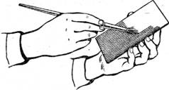
- Appointment of planar marking
- What should be used reinforcing mesh for concrete, wallpaper, plaster technology - plastic, fiberglass or metal
- Edit strip and sheet material
- Open lesson "editing, bending"
- Installation of staircases and platforms: general information
- Repair of pipes of water supply in the apartment Repair of steel pipes
- Markup definition. Planar marking. Types of markup. Questions for self-test
- Pipe bending machines Various variations of pipe bending machine
- Safety during filing