Site sections
Editor's Choice:
- Why at home may there be a need for measuring water resistance?
- Alteration of "Khrushchev" dvushki almost treshku
- Paint the wallpaper with your own hands
- Installation options for drywall in the bathroom
- Court decision on recovery from the management company of the amount of damage to the gulf of the apartment
- Living room and children in the same room: options for partitions
- Top sofa upholstery rating: customer reviews
- Expansion joints in buildings
- Chaber - what is it and its purpose
- Sharpening wood cutters: manual work, using grinding wheels and a grinding machine
Advertising
| Machining of tapered surfaces on a lathe. Processing of conic surfaces on the lathe. Processing of shaped surfaces |
|
Ways of processing of conic surfaces. The machining of tapered surfaces on lathes is carried out in the following ways: by turning the upper slide of the caliper, by transverse displacement of the body of the tailstock, using a tapered ruler, with a special wide cutter. With the use of rotation of the upper slide caliper ob-sharpen short conical surfaces with different inclination a. Upper slide caliper set on the magnitude of the slope of the divisions applied around the circumference of the support flange of the caliper. If a atthe detail drawing of the angle of inclination a is not specified, it is determined by the formula: and the table of tangents. Feed with this method of operation is performed manually by rotating the screw knob of the upper slide of the caliper. Longitudinal and transverse slides should be locked at this time. Tapered surfaces with a small angle of inclination of the cone with a relatively large length of the workpiece processwith the use of lateral displacement of the body of the tailstock.With this method of machining, the cutter moves with a longitudinal feed in the same way as when turning, cylindrical surfaces. The conical surface is formed by the displacement of the rear center of the workpiece. When the rear center is “away”, the diameter Da large base of the cone is formed at the right end of the workpiece, and when shifted “towards itself” - at the left. The amount of lateral displacement of the body of the tailstock bdetermined by the formula: where L- distance between centers (length of the whole workpiece), l - the length of the conical part. With L = l(cone along the entire length of the workpiece). If K or a is known, then, or Ltga. Back case grandmasproduce, using the divisions applied on the end of the base plate, and the risk on the end of the body of the tailstock. If there are no divisions on the end of the plate, then the body of the tailstock is displaced using a measuring ruler. Taper surface machining using a tapered rulerproduced with the simultaneous implementation of the longitudinal and transverse feeds of the cutter. Longitudinal feed is made, as usual, from the running roller, and transverse - by means of a tapered ruler. The plate is attached to the machine bed , on which the cone ruler is installed . The ruler can rotate around a finger at the required angle a ° to the axis of the workpiece being processed. The position of the ruler is fixed by bolts . The slide that slides along the ruler is connected to the lower transverse part of the support by means of a pull rod. . To this part of the caliper freely slid along its guides, it is disconnected from the carriage , removing or disabling the cross feed screw. If the carriage is now informed of the longitudinal feed, the thrust will move the slider along the tapered ruler. Since the slider is connected with the cross slide slide, they will move along with the cutter parallel to the tapered ruler. Thus, the cutter will process a conical surface with a slope angle equal to the angle of rotation of the tapered ruler. The cutting depth is set using the caliper top grip, which must be rotated 90 ° relative to its normal position. Cutting tools and cutting conditions for all considered methods of processing cones are similar to those used for turning cylindrical surfaces. Tapered surfaces with a short cone length can be machined. special wide chiselwith an angle in the plan corresponding to the angle of the slope of the cone. The cutter feed may be longitudinal or transverse. \u003e\u003e Technology: Making cylindrical and conical parts with hand tools Details of cylindrical shape, which in the cross section have the shape of a circle of constant diameter, can be made of square bars. Bars are usually cut from boards (Fig. 22, a). The thickness and width of the bar should be 1 ... 2 mm greater than the diameter of the future product, taking into account the allowance (stock) for processing. The edges of the octahedron are crushed by a Sherhebel or a plane to the marking lines of a circle (Fig. 22, c). Once again, they hold tangents to the circle, draw a line 2 along the ruler, and cut down the faces of the sixteen-square (fig. 22, d). The sequence of all the operations listed above upon receipt of a cylindrical billet from a square bar can be recorded in the route map. This map records the sequence (route, path) of processing one part. Table 2 shows the route map for the manufacture of cuttings for a shovel.
Practical work ♦ Calipers, route map. 1. What is the sequence of manufacturing parts cylindrical and conical shape? 2. How to measure the diameter of the part with calipers? 3. What is recorded in the routing process map? Simonenko V.D., Samorodsky PS, Tishchenko A.T., Technology Grade 6 The conical are the surfaces formed by the movement of the rectilinear generatrix. l along a curved rail t.The peculiarity of the formation of a conical surface is that Fig. 95 Fig. 96 however, one point of the generator is always fixed. This point is the top of the conical surface (Fig. 95, but).The taper surface identifier includes the top Sand guide t,wherein l"~ S; l"^ t. Cylindrical include surfaces formed by a direct generatrix / moving along a curved guide. tparallel to a given direction S(Fig. 95, b).A cylindrical surface can be considered as a special case of a conical surface with an infinitely distant apex. S. The determinant of the cylindrical surface consists of a guide tand directions S forming lwhile l "|| S; l "^ t. If the forming cylindrical surface is perpendicular to the plane of the projections, then such a surface is called projecting.In fig. 95, atshows a horizontally projecting cylindrical surface. On cylindrical and conical surfaces, set points are built using generators passing through them. Lines on surfaces, such as line butin fig. 95, ator horizontal hin fig. 95, a, b,are built using individual points belonging to these lines. Rotation surfaces The surfaces of revolution are those formed by rotating the line l around the straight line i, which is the axis of rotation. They may be ruled, such as a cone or cylinder of rotation, and non-linear or curvilinear, such as a sphere. The determinant of the surface of revolution includes the generator l and the axis i. Each point forming during rotation describes a circle whose plane is perpendicular to the axis of rotation. Such circles of the surface of revolution are called parallels. The greatest of parallels is called the equator.Equator. Determines the horizontal essay of the surface, if i _ | _ П 1 . In this case, the parallels are the horizontals of this surface. Curved surfaces of revolution resulting from the intersection of the surface by planes passing through the axis of rotation are called meridians.All the meridians of one surface are congruent. The frontal meridian is called the prime meridian; he determines the frontal sketch of the surface of rotation. The profile meridian determines the profile sketch of the surface of revolution. It is most convenient to build a point on curved surfaces of revolution with the help of parallel surfaces. In fig. 103 point Mbuilt on parallel h 4. Surface rotation found the widest application in technology. They limit the surfaces of most engineering parts. The conical surface of rotation is formed by the rotation of a straight line. iaround a straight line intersecting with it - the axis i (Fig. 104, a). Point Mon the surface is constructed using the generatrix l and parallel h.This surface is also called a cone of rotation or a right circular cone. The cylindrical surface of rotation is formed by rotating the straight line l around the axis i parallel to it (Fig. 104, b).This surface is also called a cylinder or a straight circular cylinder. A sphere formed by rotating a circle around its diameter (Fig. 104, c). Point A on the surface of the sphere belongs to the principal
Fig. 103
Fig. 104 meridian f,point AT- equator h,a point Mbuilt on an auxiliary parallel h ". A torus is formed by rotating a circle or its arc around an axis lying in the plane of the circle. If the axis is located within the formed circle, then such a torus is called closed (Fig. 105, a). If the axis of rotation is outside the circle, then such a torus is called open (Fig. 105, b).An open torus is also called a ring. Surfaces of revolution can also be formed by other curves of the second order. Ellipsoid of rotation (Fig. 106, but)formed by rotating an ellipse around one of its axes; paraboloid of rotation (fig. 106, b) - rotation of the parabola around its axis; A single-cavity hyperboloid of rotation (Fig. 106, c) is formed by rotating a hyperbola around the imaginary axis, and a two-cavity hyperboloid (Fig. 106, d) is formed by rotating a hyperbola around the real axis. In the general case, surfaces are depicted as not limited in the direction of propagation of the forming lines (see figs. 97, 98). To solve specific problems and obtain geometric shapes are limited to the planes of the crop. For example, to obtain a circular cylinder, it is necessary to limit the portion of the cylindrical surface to the cut planes (see Fig. 104, b).As a result, we obtain its upper and lower bases. If the cutting planes are perpendicular to the axis of rotation, the cylinder will be straight, if not, the cylinder will be inclined.
Fig. 105 Fig. 106 To get a circular cone (see fig. 104, a), it is necessary to cut along the top and beyond. If the cutting plane of the cylinder base is perpendicular to the axis of rotation, the cone will be straight, if not, it will be inclined. If both cutting planes do not pass through the top - the cone will get truncated. Using the plane of the crop, you can get a prism and a pyramid. For example, a hexagonal pyramid will be straight if all its edges have the same inclination to the trimming plane. In other cases, it will be inclined. If it is done withusing cutting planes, and none of them passes through the top — the pyramid is truncated. A prism (see fig. 101) can be obtained by limiting a portion of the prismatic surface to two planes of the crop. If the cut plane is perpendicular to the edges, for example, an octagonal prism, it is straight, if not perpendicular, it is inclined. By choosing the appropriate position of the cutting planes, one can obtain various forms of geometric shapes depending on the conditions of the problem being solved. Question 22 Paraboloid - a type of surface of the second order. A paraboloid can be characterized as an open, non-central (that is, without a center of symmetry) surface of the second order. The canonical paraboloid equations in Cartesian coordinates: 2z = x 2 / p + y 2 / q If p and q are of the same sign, then the paraboloid is called elliptical. if a different sign, then the paraboloid is called hyperbolic. if one of the coefficients is zero, then the paraboloid is called a parabolic cylinder.
Elliptical Paraboloid 2z = x 2 / p + y 2 / q
Elliptical parabloid if p = q 2z = x 2 / p + y 2 / q
2z = x 2 / p-y 2 / q
Parabolic cylinder 2z = x 2 / p (or 2z = y 2 / q) Question23 Real linear space is called Euclidean if it defines an operation scalar multiplication : a real number is associated with any two vectors x and y ( denoted by (x, y) ), and this respectively satisfies the following conditions, whatever the vectors x, y and z and the number C: 2. (x + y, z) = (x, z) + (y, z) 3. (Cx, y) = C (x, y) 4. (x, x)\u003e 0 if x ≠ 0 The simplest consequences of the above axioms: 1. (x, Cy) = (Cy, x) = C (y, x) therefore always (X, Cy) = C (x, y) 2. (x, y + z) = (x, y) + (x, z) 3. () = (x i, y) ( Conical holes are bored, usually by turning the top of the caliper to the desired angle. The boring tool is installed in the tool holder in the center of the machine axis and secured. The rotary part of the caliper together with the cutter is placed at the desired angle to the axis of the centers of the machine and secured. After finishing boring the hole on the cone, it is unrolled by a conic scan of the corresponding taper. It is more profitable to taper taper holes directly after drilling with a set of special reamers that have the same taper. Three sweeps are applied successively - rough, semi-finishing and finishing. Rough scan remove the largest allowance. To facilitate the work of the rough scan, its cutting edges make stepped, with round grooves for crushing chips. The grooves have a helix. The rough-scanned surface is usually rough, with screw grooves on the walls.
The half-turn reamer, unlike the rough one, has smaller grooves for cutting chips on the cutting edges. Due to this, the treated surface is cleaner, but the screw grooves on the walls remain. Finishing reamer manufactured with solid rectilinear cutting edges. It gives the hole final dimensions and a smooth surface.
Questions
Taper surface machining controlIn mass production, conical surfaces are checked with unregulated or adjustable patterns. The diameters of flat conical surfaces are checked with a caliper or micrometer (depending on the accuracy of the machined part). External cones are checked with gauge-sleeves. Control the outer conical surface as follows. Caliber sleeve put on the checked surface of the cone details. If the gauge does not swing, then the taper is correct. More precisely, the control of taper on the color. To control, a thin layer of paint is evenly applied to the tested surface of the cone of the part. Then put a gauge sleeve on the cone of the part and turn it half a turn. If the paint is removed from the surface of the cone parts unevenly, it indicates inaccuracy and the cone must be fixed. Erasing paint from a smaller diameter of the cone will show that the angle of inclination of the cone is small, and, conversely, erasing paint from a larger diameter will show that the angle of inclination of the cone is large. The diameters of the outer cone are checked with the same gauge bushing. When putting the sleeve on the correctly treated cone, its end must coincide with the risk on the cut part of the sleeve.
If the end of the cone does not reach the risks, further processing is necessary; if, on the contrary, the end of the cone has passed the risk, the part is rejected. Conical holes are controlled with plug gauges. Do it like this. A plug gauge, having two risks, is inserted, pressing lightly, into the hole and it is noticed that the gauge does not swing in the hole. The lack of swing indicates that the angle of the cone is correct.
Making sure of this, proceed to check the diameters of the tapered bore. To do this, observe to what place the gauge will enter the hole being tested. If the end of the hole coincides with one of the scratches or is between the caliber risks, the dimensions of the cone are correct. When both caliber risks enter the hole, it shows that the diameter of the hole is larger than the specified. If both risks are outside the hole, its diameter is less than the required one. Questions
"Plumbing", IG Spiridonov,
In the sixth and seventh grades, you became acquainted with various works performed on a lathe (for example, external cylindrical turning, cutting parts, drilling). Many workpieces machined on lathes may have an outer or inner conical surface. Details with a conical surface are widely used in mechanical engineering (for example, the spindle of a drilling machine, the shanks of drills, the centers of the lathe, the hole of the tailstock quill) ....
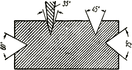
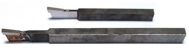
Wide incisors process cones up to 20 mm in length on rigid parts. At the same time achieve high performance, but the purity and accuracy of processing are low. Handle the tapered surface. The workpiece is clamped in the cartridge of the headstock. Processing a conic surface with a wide cutter. The end of the workpiece to be machined should protrude no more than 2.0 to 2.5 times the diameter of the workpiece from the cartridge. The main cutting edge of the tool ... When processing conical surfaces, the following types of defects are possible: irregular taper, deviations in the sizes of the cone, deviations in the sizes of the diameters of the bases with the correct taper, non-linearity of the generatrix of the conical surface. Incorrect taper is obtained mainly due to inaccurately set cutter, inaccurate rotation of the upper part of the caliper. Checking the installation of the body of the tailstock, the top of the caliper before starting treatment, you can prevent this type ... Processing center holes. Inspection of conical surfaces Machining center holes. In parts such as shafts, it is often necessary to carry out center holes, which are used for further processing of the part and for restoring it during operation. Therefore, the centering is performed very carefully. The center holes of the shaft must be on the same axis and have the same dimensions at both ends, regardless of the diameters of the end necks of the shaft. If these requirements are not met, the accuracy of processing decreases and the wear of the centers and center holes increases. The design of the center holes is shown in Figure 40, their dimensions are in the table below. Center openings with a cone angle of 60 degrees are most common. Sometimes in heavy shafts this angle is increased to 75 or 90 degrees. In order for the top of the center not to rest against the workpiece, cylindrical recesses with a diameter d are made in the center holes. To protect against damage, reusable center holes are made with a safety bevel at an angle of 120 degrees (Figure 40 b). Fig. 40. Center holes
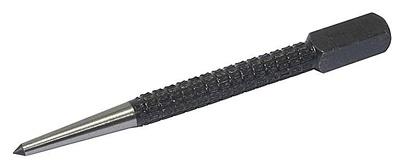
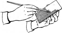
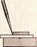
Figure 41 shows how the rear center of the machine wears when the center hole in the workpiece is incorrectly made. When the misalignment (a) of the center hole and the misalignment (b) of the centers, the part during processing is skewed, which causes significant errors in the shape of the outer surface of the part. Center holes in small blanks are processed by various methods. The billet is fixed in a self-centering chuck, and a drill chuck with a centering tool is inserted into the tailstock quill. Fig. 41. Wear the rear center of the machine Center holes with a diameter of 1.5-5 mm are machined with combined center drills without a safety chamfer (figure 42g) and with a safety chamfer (right figure 41e). The center holes of large sizes are treated first with a cylindrical drill (figure 41a on the right), and then with a single-tooth (figure 41b) or multi-bit (figure 41c) countersink. Center holes are machined with a rotating workpiece; The centering tool is fed manually (from the tailstock flywheel). The butt, in which the center hole is machined, is preliminarily trimmed with a chisel. The required size of the center hole is determined by the deepening of the centering tool, using the tailstock flywheel dial or quill scale. To ensure the alignment of the center holes, the detail is pre-marked, and when centered, it is supported by a steady. Fig. 41. Drill for centering holes Center holes are marked out using a marking square (Figure 42a). Pins 1 and 2 are located at an equal distance from the edge AA of the square. Putting a square on the end and pressing the pins to the shaft neck, along the edge of the AA, they risk at the shaft end, and then, turning the angle bar 60-90 degrees, carry out the following risk, etc. The intersection of several scratches will determine the position of the center hole on the shaft end. For marking, you can also use the square, shown in Figure 42b. After marking make centering holes centering. If the diameter of the shaft journal does not exceed 40 mm, then it is possible to make a centering hole without prior marking using the tool shown in Figure 42c. The housing 1 devices set with his left hand at the end of the shaft 3 and a hammer with a center punch 2 mark the center of the hole. If during operation the conical surfaces of the center holes were damaged or unevenly worn, then they can be corrected with a chisel; while the upper carriage caliper is rotated at a cone angle. Fig. 42. Marking centering holes Inspection of conical surfaces. The taper of the outer conical surfaces is measured with a template or universal goniometer. For more accurate measurements, gauge sleeves are used, figure d) and d) on the left, with which they check not only the angle of the cone, but also its diameters. 2-3 risks are applied to the processed surface of the cone with a pencil, then a gauge sleeve is put on the measuring cone, slightly pressing it and turning it along the axis. With a properly made cone, all risks are erased, and the end of the conical part is between the marks A and B of the caliber bushing. When measuring the tapered bore, a gauge plug is used. The correctness of the processing of the tapered bore is determined (as in the measurement of external cones) by the mutual fit of the surfaces of the part and the gauge-plug. If the risks caused by a pencil on a gauge plug are erased at a small diameter, the angle of the cone in the part is large, and if the diameter is large, the angle is small. |


 Hyperbolic Paraboloid


Popular:
New
- How to rivet a rivet - automatic and manual methods for different materials What rivet rivet steel sheets
- Appointment of planar marking
- What should be used reinforcing mesh for concrete, wallpaper, plaster technology - plastic, fiberglass or metal
- Edit strip and sheet material
- Open lesson "editing, bending"
- Installation of staircases and platforms: general information
- Repair of pipes of water supply in the apartment Repair of steel pipes
- Markup definition. Planar marking. Types of markup. Questions for self-test
- Pipe bending machines Various variations of pipe bending machine
- Safety during filing