Site sections
Editor's Choice:
- Bathroom faucet device with shower - repair
- If noise interferes with neighbors (memo)
- Why at home may there be a need for measuring water resistance?
- Alteration of "Khrushchev" dvushki almost treshku
- Paint the wallpaper with your own hands
- Installation options for drywall in the bathroom
- Court decision on recovery from the management company of the amount of damage to the gulf of the apartment
- Living room and children in the same room: options for partitions
- Top sofa upholstery rating: customer reviews
- Expansion joints in buildings
Advertising
| Determine the thread pitch using calipers. How to measure with a caliper: examples. Geometric parameters of thread |
|
Metric thread is a screw thread on the outer or inner surfaces of products. The shape of the protrusions and hollows that form it is an isosceles triangle. Metric this thread is called because all its geometrical parameters are measured in millimeters. It can be applied on the surface of both cylindrical and conical shape and used for the manufacture of fasteners for various purposes. In addition, depending on the direction of elevation of the turns, the metric-type thread is right or left. In addition to the metric, as is well known, there are other types of thread - inch, pitchevaya, etc. A separate category is modular thread, which is used to manufacture elements of worm gears. Basic parameters and scopeThe most common is metric thread applied to the outer and inner surfaces of a cylindrical shape. That it is most often used in the manufacture of fasteners of various types:
Conical-shaped parts, on the surface of which a metric-type thread is applied, are required in cases where the created joint needs to be given a high tightness. The profile of the metric thread applied to the tapered surfaces allows to form tight joints even without the use of additional sealing elements. That is why it is successfully used in the installation of pipelines through which various media are transported, as well as in the manufacture of plugs for containers containing liquid and gaseous substances. It should be borne in mind that the thread profile of the metric type is the same on cylindrical and on conical surfaces.
Types of threads related to the metric type, distinguished by a number of parameters, which include:
There are additional parameters, depending on which metric threads are divided into different types.
Geometric parametersConsider the geometric parameters that characterize the main elements of the thread of the metric type.
The table of values of diameters of a metric thread (all parameters are specified in millimeters) Values of diameters of a metric thread (mm) Full table of metric threads according to GOST 24705-2004 (all parameters are in millimeters) Full table of metric threads according to GOST 24705-2004 The main parameters of the metric thread type are specified in several regulatory documents.GOST 8724 This standard contains requirements for the parameters of the thread pitch and its diameter. GOST 8724, the current edition of which entered into force in 2004, is the equivalent of the international standard ISO 261-98. The requirements of the latter apply to metric threads with a diameter of 1 to 300 mm. Compared with this document, GOST 8724 is valid for a wider range of diameters (0.25–600 mm). At present, the current edition of GOST 8724 2002, which came into effect in 2004 instead of GOST 8724 81, is relevant. It should be borne in mind that GOST 8724 regulates certain parameters of a metric thread, the requirements for which are stipulated by other thread standards. The convenience of using GOST 8724 2002 (as well as other similar documents) is that all the information in it is contained in the tables, which include metric threads with diameters that are in the above range. The requirements of this standard must meet both the left and right thread metric type. GOST 24705 2004This standard specifies what should be the metric thread of basic dimensions. GOST 24705 2004 applies to all threads, the requirements for which are governed by GOST 8724 2002, as well as GOST 9150 2002. GOST 9150This is a regulatory document, which specifies the requirements for the profile of a metric thread. GOST 9150, in particular, contains data on which geometrical parameters should correspond to the main threaded profile of various sizes. The requirements of GOST 9150, developed in 2002, as well as the two previous standards, apply to metric threads, the turns of which rise from the left upwards (of the right type), and those whose helix rises to the left (of the left type). The provisions of this regulatory document closely overlap with the requirements of GOST 16093 (as well as GOST 24705 and 8724). GOST 16093This standard specifies requirements for tolerances on metric threads. In addition, GOST 16093 dictates how the marking of the thread of a metric type should be carried out. GOST 16093 in the latest edition, which came into effect in 2005, includes the provisions of international standards ISO 965-1 and ISO 965-3. The requirements of such a regulatory document as GOST 16093, includes both left and right thread. The standardized parameters specified in the metric-type thread tables should correspond to the dimensions of the thread in the drawing of the future product. The choice of the tool with which it will be cut should be determined by these parameters. Rules of designationTo denote the tolerance field of a separate diameter of a metric thread, a combination of a digit is used, which indicates the accuracy class of the thread, and the letter defining the main deviation. The thread tolerance area must also be indicated by two alphanumeric elements: in the first place - the tolerance field d2 (average diameter), in the second - the tolerance field d (outer diameter). In that case, if the tolerance fields of the outer and middle diameters coincide, then they are not repeated in the designation.
According to the rules, the first designation is the designation of the thread, followed by the designation of the tolerance field. It should be borne in mind that the thread pitch is not indicated in the marking. You can learn this parameter from special tables. The designation of the thread also indicates to which group it belongs to the length of the screwing. In total there are three such groups:
The letters S and L, if necessary, follow the designation of the tolerance field and are separated from it by a long horizontal line.
Be sure to indicate such an important parameter as the fit of the threaded connection. This fraction is formed as follows: in the numerator is affixed with the designation of the internal thread, referring to the field of its tolerance, and in the denominator - the designation of the tolerance field on the thread of the external type.
Tolerance FieldsThe tolerance fields for the metric threaded element can be of one of three types:
It would seem that in the pipes of the complex? Connect and cool ... But, if you are not a plumber and not an engineer with specialized education, then questions will surely arise, for answers to which you have to go where your eyes are. And they look most likely the first thing on the Internet) We have already talked about the diameters of metal pipes in this material. Today we will try to clarify the threaded connections of pipes for various purposes. We tried not to overload the article with definitions. Basic terminology contains GOST 11708-82 with which everyone can familiarize themselves. Pipe cylindrical thread. GOST 6357 - 81
Direction: Left Accuracy class: Class A (increased), Class B (normal)
This type of thread is used both in the pipes themselves and in the elements of pipe joints: lock nuts, couplings, elbows, tees ( see picture above). In the section of the profile, we see an isosceles triangle with an angle of 55 degrees and roundings on the tops and valleys of the contour, which are performed for high tightness of the joint. Threaded connections are made on sizes up to 6 ”. All pipes of larger size for reliability of connection and prevent rupture are fixed by welding. Symbol in the international standardInternational: G Japan: PF United Kingdom: BSPP Indicates the letter G and the diameter of the bore (internal Ø) of the pipe in inches. The outer diameter of the thread itself is not present in the designation. Example: G 1/2 - external cylindrical pipe thread, internal pipe Ø 1/2 "". The outer diameter of the pipe will be 20.995 mm, the number of steps on a length of 25.4 mm will be 14. The accuracy class (A, B) and the direction of the coils (LH) can also be indicated. For example: G 1 ½ - B - cylindrical pipe thread, internal Ø 1 ½ ”, accuracy class B. G1 ½ LH- B - cylindrical pipe thread, internal Ø 1 ½ inch, accuracy class B, left. The fastening length is indicated last in mm: G 1 ½ -В-40. For an internal pipe cylindrical thread, only the pipe Ø for which the hole is intended will be indicated. Tube size table
How to determine the pitch of the inch thread
I bring you a picture from the English-language Internet, which clearly demonstrates the technique. Pipe threads are not characterized by the size between the profile tops, but by the number of turns per inch along the thread axis. To help ordinary roulette or ruler. We apply, measure one inch (25.4 mm) and count the number of steps visually. In the picture with an example ( see above) threads - from English it is literally "thread thread." In this case, there are 18 of them. by one inch. It is even easier if the thread gauge for the inch thread was in the box in your tool box. Measurements are very convenient to carry out, but it must be remembered that the thread may vary in the apex angle of 55 ° and 60 °. Tapered pipe threads
drawing pipe tapered threads Conical pipe thread GOST 6211-81 (1st size)Unit of measurement: Inch Corresponds to the rounded profile of a pipe cylindrical thread with an angle of 55 °. Cm. top Part (I) of the three-dimensional image "drawing pipe tapered threads". SymbolInternational: R Japan: PT United Kingdom: BSPT Indicates the letter R and the nominal diameter Dy. The designation R means the external appearance of the thread, Rc internal, Rp internal cylindrical. By analogy with a cylindrical pipe thread for the left-hand thread is used LH. Examples: R1 ½ - external pipe tapered thread, nominal diameter Dy = 1 ½ inch. R1 ½ LH - external pipe tapered thread, nominal diameter Dy = 1 ½ inch, left. Conical inch thread GOST 6111 - 52 (2nd type)Unit of measurement: Inch Has a profile angle of 60 °. Cm. lower Part (II) of the three-dimensional image "drawing pipe tapered threads". It is used in pipelines (fuel, water, air) machines and machines with relatively low pressure. The use of this type of connection implies tightness and thread locking without additional special means (flax, yarn with red lead). SymbolExample: K ½ GOST 6111 - 52 It stands for: conical inch thread with external and internal diameter in the main plane approximately equal to the external and internal Ø of a pipe cylindrical thread G ½ Table of the main parameters of the tapered inch thread
Metric tapered thread. GOST 25229 - 82
Unit of measurement: mm Made on taper surfaces 1:16 Used when connecting pipelines. The angle at the top of the coil is 60 °. The main plane is offset from the end ( see pic above). SymbolFollowing the letters MK is an indication of the diameter in the main plane and the thread pitch in mm: MK 30x2 Size table for metric tapered threads
The characteristic of the cylindrical pipe / inch thread relative to the metricThe main characteristics of "inch" and "pipe" cylindrical threads in relation to the "metric" thread for basic sizes.
The quality of the thread that is cut on the water pipe, as well as its relation to the pipe axis, is extremely important when installing water supply or heating. Manual cutting with a die is not particularly effective - it is much more convenient when the thread is metric and pipe cut with a chisel using a lathe. What is a pipe thread?A thread is called a helical groove with a constant pitch and cross section, which is applied to the surface of machine parts of a weakly conical or cylindrical shape, such as bolts, screws, and also on the surfaces of parts connected to them — for example, nuts. In the home, you have to deal mainly with. Along with metric threads, inch pipe threads are very successfully used in our country. The main characteristics of a metric thread are the pitch (the distance from one depression to another or between the crests of the thread, measured along the detailed axis, which is expressed in millimeters) and the diameter. The main parameters of the inch is the diameter, expressed in inches or parts of an inch, as well as the number of turns cut into an inch. Here it must be recalled that one inch is 25.4 mm. An example for consideration is the cylindrical pipe inch thread of the GOST - most often you have to work with it. There will have to meet with a somewhat unusual unit of measurement - this is the "tube inch", which is equal to 33, 249 mm. It turned out as follows: to the size in inches, which characterizes the internal diameter of the pipe, they added the thickness of both walls. The result was the following result:
The inch thread pipe GOST differs from metric, in addition to the features already described, by the following nuances:
Threads used in everyday lifeIn everyday life, pipes with the following types of threads are most commonly used:
Pipe threadingDetermination of pipe thread pitchTo determine the type, as well as the pitch of the pipe thread, use a tool called thread gauge. You can also use a ruler or a caliper. When determining the pitch of a metric thread, the distance between the vertices of several threads is measured, after which the distance is divided by the number of threads. In the presence of an inch thread, threads are counted, which can fit in one inch (25.4 mm). In practice, of course, it’s hardly possible for someone to ensure such a diameter accuracy, but one can hope to get a completely satisfactory thread, guided by at least one figure that comes after the comma.
Pipe threadingPerformed metric and pipe thread something like this. If this operation is performed manually, and not with a lathe, its implementation is associated with additional difficulties - especially for those with a diameter greater than one inch. The most convenient way is to use a special device for cutting threads manually (KLUP). The device is a body with two handles, where adjustable movable combs are placed, with which the pipe metric thread gradually deepens to the full profile. In addition, you can use interchangeable combs with a full thread profile and an incomplete profile. This tool does not belong to the category of cheap, and since it is not available to everyone, we can mention several devices for ordinary meter (it is also called a die), with the help of which the actual pipe thread is metric. When rotating the ring holder clockwise, it is screwed onto the thread on the sleeve, which, in turn, is fixed on the pipe with three bolts. Such a device has indisputable advantages: there is no “stop” in the pipe at the primary stage of cutting, since pipe and metric threads are easily realized with the sleeve fixed on the pipe.
Metric pipe thread, which is cut by ring holders without extension cords or similar devices, in most cases does not hold up to criticism. They can be equipped with lathe inserts.
The total length of the liners - 100-150 mm. The product itself is a liner with a hole where the stud is inserted - on one side there is an external thread, on the other side there is a tapered section. In other words, on the one hand the insert has a thread, on the other hand - a cylindrical segment, on the lower part of which there are grooves. The diameter of the cylindrical section should be somewhat smaller than the internal diameter of the pipe D, on which the pipe metric thread should be cut. In the walls of this cylinder, three longitudinal slits are made in the lower part (just like at the collet), and if you tighten the pin with a nut inside the insert, the cylinder expands under the influence of the tapered section of the pin and wedges the insert in the pipe. Before starting work, a gauge with a lee-holder is screwed onto the threaded part of the liner, then the liner is inserted into the pipe as far as it will go with the gauge; Thus, fixing (wedging) of the liner in the tube is achieved. The metric pipe thread is cut clockwise by rotating the holder, the gauge is transferred from the thread of the liner to the pipe. Correctly made pipe thread will be the key to success with regard to the tightness of pipe connections, and will serve, during the entire period of operation, directly, the pipes themselves. Without fasteners the master as without hands: it is necessary to deal with a fixed connection of parts of various designs constantly. Bolts, screws, nuts, screws, washers - the most running fasteners. In the work it is often important to know in advance the size of the bolt. You will need Calipers; P & G Placement Sponsor "How to determine the bolt size" How to determine the size of a gas mask How to find out the size of your hand Instruction Bolts and nuts, similar to modern ones, appeared around the middle of the 15th century. They were made entirely by hand, and therefore each nut-bolt combination was unique. The classic version of the combination of these two parts over the years improved. Among the latest industrial advances is the development of special electronic devices capable of automatically controlling the tightening forces of this type of fastener. Modern bolt - claimed fastener. Together with the nut, it is intended for detachable connection of parts and is a cylindrical rod with an external thread at one end and a head at the other. The head can be of different shapes: square, oval, cylindrical, conical, of six or four faces. Most of the state standards for fasteners, including bolts, provide for the possibility of producing similar products (by general form, by purpose). The difference will be only in the type of bolts and their performance. The size of the bolt depends on the purpose and is primarily related to the outer diameter of the thread, since the bolt is a threaded fastener. To determine the diameter of the bolt, measure its outer diameter with a caliper thread. If the thread is not applied along the entire length of the rod, then the diameter of the bolt in its “bald” part is approximately the same as the diameter of the thread when measured at the tops of the turns. What is considered the length of the bolt? As a rule, the designation of the product indicates the length of its core. Thus, the height of the head is not taken into account. Measure the length of the rod - get the length of the bolt. If you order the M14x140 bolt in the metric measurement, this means you need a bolt with a thread diameter of 14 mm and a rod length of 140 mm. In this case, the overall overall length of the product, taking into account the height of the bolt head, for example, 8 mm will be 148 mm. Another parameter is the bolt thread pitch. Measure the distance between two nearby (adjacent) tops of the thread and you will get the desired size. For example, the M14x1,5 bolt is a bolt with a diameter of 14 mm and a thread pitch of 1.5 mm. Another characteristic of some types of bolts in size is the length of the threaded end. To find out, measure the part of the rod that is designed to screw the nut. There are many standards that set out the technical requirements for fasteners. For example, for flange connections (namely, bolts are used for them) they are set forth in GOST 20700-75. And the design, and the size of fasteners are governed by GOST 9064-75,9065-75, 9066-75. How simple Other related news: Cutting ... If the holes are drilled in order to bolt the workpieces, it is necessary to take a drill with a diameter slightly larger than the diameter of the bolt by 0.5-1mm. Such a gap compensates for possible inaccuracies in the position of the holes in the blanks. By the way, to reduce these inaccuracies, it is recommended to connect The thread can be different: artistic, where the picture is cut on the material, or machine-building, which is a spiral screw cut, made on a round rod, or in a hole. About one such thread of the many varieties of them used in mechanical engineering and life, A rare fan of technology at least once did not come across an annoying situation when instead of a whole bolt in his hands there was a head with a short stump. The rest of the bolt got stuck in the hole, and removing it turned into extra trouble and wasted time. How to turn out Sometimes it happens that when tightening new bolts, excessive force is applied and the bolt breaks, and also when twisting the old rusted bolts, you have to deal with bolts with a broken thread or a broken head. In this case, there are several techniques to remove such a bolt. When there are problems with the car, someone is looking for a good car service, and someone is trying to deal with the problem on their own. If this problem is really serious, then it is better not to experiment and immediately turn to the professionals. But there are some faults that you may well Drawing is one of the most important disciplines in technical and engineering specialties, since it depends on the correctness and accuracy of the drawings of various parts how correctly they will be made in reality. Among the most simple drawings can distinguish tracing nuts and bolts - Caliper is a convenient and easy to use measuring tool. Proper use of it allows you to perform measurements of linear quantities in various situations, and for a variety of objects, ranging from tire tread, and ending with plastic flexible tubes. How to measure with a caliper — examples and sequence — these are discussed further. Measurements in the design and manufacture of threaded connectionsThe bolt-nut connection is one of the most common in mechanics. In the design and manufacture of structures, the task — how to measure a bolt with a caliper — often presents difficulties. Before work it is worth remembering that the main dimensions of the bolt / nut are the length of the product and the diameter of the thread. A standard bolt of any design does not require such measurements. It is a different matter when the bolt is made in artisanal conditions, or it is required to measure the fastener without dismantling the connection. The following situations are possible here: Measuring the size of the pattern on the protectorsHow to measure tire tread, if you need to assess the degree of wear? It will help the depth gauge, which measures the entire tire tread component. It should be noted that the wear is almost always uneven, and the number of measurements must be at least 3 ... 5, moreover, on the tire tread sections equally accepted for evaluation. Before measuring, the tire should be thoroughly cleaned of dirt, dust, and fragments of small stones stuck inside.
Sometimes it is necessary to solve the problem - how to measure the tire tread with a caliper to determine the degree of uniformity of wear. This establishes tire tread wear not only in depth, but also in the radius of the transition from the circumference of the projections to the circumference of the depressions. Do this. The depth of the pattern on the new tire tread is measured, and then the linear dimension of the visually modified zone on the operated part. The difference will determine the degree of wear and help you make the right decision about replacing the wheel. All measurements are made with a depth gauge, which must be installed strictly perpendicular to the tire tread generator.
Measuring tread wear by Columbic Diameter measurementsHow to measure the diameter of a caliper? Distinguish parts with constant and variable in length section. The latter include, in particular, reinforcing bars. How to measure the diameter of the valve with a caliper? It all depends on the reinforcement profile, which can be:
The easiest way to measure such parameters of reinforcement in the second case. Initially, the external measuring jaws determine the height of the protrusions of the profile, and then the depth gauge determines the size of the cavity. Measurements must be made in two mutually perpendicular directions, since fittings, and even not manufactured by specialized enterprises, often have a section ovality. After that, according to the tables of standard reinforcing profiles, find the most appropriate value (special accuracy is not required here). How to measure the diameter of the reinforcement with a caliper, if it has a different type of profile? Here, instead of the diameter of the protrusions, the diameter of the protruding part of the crescent-shaped notches is determined, and then they act in the same way as the previous case.
When measuring the internal dimensions of the pipe using the internal measuring scale of the instrument. How to measure the thickness of a pipe with a caliper, especially if the clearance is small? It is enough to calculate the difference between the external and internal diameters and divide the result into two. Linear DimensionsHow to measure linear dimensions with a caliper? It all depends on the material of the part / workpiece. For rigid elements, the product is tightly pressed to some kind of support plate, after which the external measuring jaws of the instrument measure. You must first determine the suitability of the existing type of caliper work. For example, the main measuring scale on the rod should be longer than the part by less than 25 ... 30 mm (taking into account the intrinsic width of the jaws). When using a depth gauge, this value is even smaller, since the frame length should also be taken into account (for the most common instruments, 0–150 mm and accuracy from 0.05 to 0.1 mm, this parameter is assumed to be at least 50 mm). How to measure the wire cross section with a caliper? Non-metallic products are flexible, and therefore significantly distort the result obtained in the usual way. Therefore, a rigid steel part (screw, nail, bar piece) should be inserted into the cambric, after which the diameter of the wire cross section can be determined with external jaws. Do the same if you want to know the internal size of the wire.
The question - how to measure a chain with a caliper - is often asked by cyclists, since the wear of a chain, defined as the distance between its adjacent links, allows you to make a decision about replacing the product. The outer jaws are set to a distance of 119 mm and injected into the link, after which they are stretched sideways, until a further increase in size proves impossible (to facilitate the work, the chain can be preloaded with a tensile force). Deviation from the original size will show the actual wear, which then must be compared with the maximum allowable. If you find an error, please highlight a piece of text and click Ctrl + Enter. The nut is a fastener screw gear or a threaded connection. They differ from other parts with a threaded hole. Together with the bolt (screw), it forms a screw pair. Nuts that are screwed onto a stud or bolt constitute a bolted joint. Most often, hexagon nuts are manufactured at the production sites. They are specially made under the wrench. Also on sale you can still find the nuts with protrusions "sheep", square shape, round with notched and other shapes. They are made from automatic steel. For this purpose, special automatic machines are used. It should be noted that nuts differ in another class of strength. So, for nuts made of carbon alloyed or unalloyed steel, the strength class is 4-6, 8-10. For nuts having a normal height (more than 0.8d), the strength class is set to 12. Those nuts that have a height of 0.5d-0.8d have a strength class of 04-05. The shape of the nut is also different. There are wing open and closed (determined by GOST 3032-76), hexagonal castellated round, hexagonal slotted (determined by GOST 6393-73, 11871-80). There are lower hexagonal nuts, especially high, high and of normal height. Hexagonal crown nuts, slotted and hexagonal nuts can be lightened (with small external dimensions), as well as normal (photo 1). Hexagon nuts are considered the most common. Koronchatye and slotted nuts are used when it is necessary to lock the nuts with cotter pins. Round nuts are used for fastening different parts, well, for connections that need to be constantly assembled and disassembled, it is best to use wing nuts, which can be easily tightened without even using a special wrench. By the way, if you need to use a large number of nuts in your work, then it is more expedient to take lightweight ones, since they will save a lot of weight. When you can see that the bolt tension rod is underloaded, it is best to use low nuts. To protect the threads from wear and tear, as well as buckling with frequent unscrewing and, use especially high nuts or high (photo 2).
Even a person who is far from the equipment often has to unscrew-tighten screws, bolts, nuts (hardware - these metal products are often abbreviated as such) with a tool designed for this purpose - wrenches. On each key is applied the size of its working part, simply - pharynx. But the value corresponding to it - the turnkey size - denoted by the letter S in technical references (the distance between the opposite parallel faces on the nut, the head of the bolt or screw), is not indicated on any fastener. There is no, as a rule, these data and in the instructions for operation and repair attached to any equipment even in designations and drawings, although there is plenty of other information about fasteners in them: the size of the thread, its pitch, sometimes length and even type of heat treatment, and often the torque. But basically these data are constructive, and they are needed for the manufacture of parts. When adjusting, repair or assembly work, the above thread parameters, except for the latter, turn out to be unclaimed. For a mechanic, it is much more important to know with what size of the throat a key is needed for the head of one or another screw or bolt and nut (or, as the professionals say, “how much key”). When a nut or a bolt head is in sight and in an easily accessible place, it’s easy to determine how much the key is needed - the technician can recognize this at a glance, and the inexperienced can “calculate” with calipers or by selecting keys: -Three times it is usually possible to do. If the fastener is located in an inaccessible place, and even “behind the eyes” (which happens very often), then it is necessary to touch the size of the turnkey head of the hardware, when even a professional can easily be mistaken. Troubles will not happen if the master tries to work with a smaller key - he simply does not fit into the head. If the key is great, then “cut off” the edges of the head, as they say, a couple of trivia. In addition, the part will be irreparably damaged, then unscrewing the fastener even with a special tool will be a considerable problem.
To determine the size of "turnkey" "for the eyes" it makes sense to refer to the information on the thread of the fastener specified in the instructions. After all, according to GOST, each closet corresponds to two close sizes of the fastener head on a turnkey basis: the main and the reduced, and the difference in their values is small. On the average, the “turnkey” size is approximately 1.5 times the outer diameter of the thread (see table 1) and it is already possible to orient to it. And although the reduced turnkey size is assigned by designers less often than the main one, it is necessary for the above reasons to try to unscrew the fasteners with a smaller key: if it does not fit, then you can safely work with a key corresponding to the main size - it will not break (of course provided that the fasteners are not rusted). The keys are usually also made according to the same principle: at one end of the pharynx (open - for carob screws, closed - for socket and ring keys) corresponds to the main size of the fastener head, on the other - reduced. Only combined keys fall out of this row, which have both ends of the pharynx of the same size, only one open and the other closed (circular), and the keys are adjustable. Matching the dimensions of the fastener “turnkey” to its nominal diameter of a metric thread
When working with fasteners for their safety, the tool is of paramount importance; therefore, you should use only serviceable keys: they should not have an extended pharynx, and a sponge crumpled. Keys with such defects must be removed from the working set. In addition, similar tools differ significantly in quality of metal, profile of sponges. The latter condition directly affects the distribution of forces on the edges and edges of the hardware. Fasteners are designed for a specific torque when assembling the product. However, often the efforts during disassembly, especially of “stuck” or rusted threaded connections, exceed it many times. In these cases it is better to use the corresponding end or ring (professionals call them spanner) keys, rather than carob keys. Moreover, you can not use a wrench, as well as when unscrewing small (less than S10) nuts, bolts and screws.
Combined pipe wrench. If the edges of the fastener are heavily damaged by corrosion or for some reason turned out to be "rolled up", in order to still unscrew it, it is necessary to grind off the edges of the key to the "number" less. Then, soaking the threaded joint with a special fluid (or, in extreme cases, with kerosene) to soften the rust and after waiting time, try again to unscrew the part. Another way (but not the last) to loosen the bolt or screw with a damaged head is to make a slot between the opposite sides under a strong screwdriver and try to unscrew the fasteners with this tool. And finally - use a pipe wrench for this. By the way, in the nomenclature of the latter there are now those that do not damage the edges and edges of fasteners, even with large unscrewing points. For small nuts, special pliers can be used.
When adjusting and repairing the same equipment (for example, a private car) has to be done regularly, it will be useful to draw up a table of the turnkey dimensions of fasteners for the main adjustable units, devoting special time to this or as you adjust to adjusting a particular mechanism or assembly.
Conventional key heads: Key heads with dynamic profiles: and - face; b - cap. Efforts on the verge and edges of the mounting threaded parts from the end (a) and cap (b) keys with different internal profiles: I - focused; II - distributed. Table 2 shows the turnkey dimensions of the main and adjusting threaded connections for VAZ-2105. Some fasteners and their dimensions "turnkey" in cars VAZ
Since we are talking about cars, it is worth noting that on a special account in the tool kit "Lada" (and other cars) the so-called "balloon" "19" and "candlestick" "21" keys. The first is made quite peculiar and stands out from the entire set of keys. He is recognized even by one who has little knowledge of technology: he is cap-shaped, with a curved handle-lever, the end of which is made in the form of a screwdriver's tip. Once with this key they removed the chrome wheel caps that are no longer installed on modern cars. It would be advisable to sharpen it a little and thus have a strong screwdriver in the kit. In addition to loosening-tightening wheel bolts, this key can be used when working with other relevant fasteners. If necessary, the wheel bolts can be unscrewed with the usual (cap and even open-ended) wrench “for 19 ″. The second one - the “candle” key looks like similar tubular end wrenches with the same diametrical hole for the knob. It even maintains a ratio of 1.5 times the diameter of the thread being turned (14 mm) to the distance between the opposite sides of the key (21 mm). If we again refer to table 2, it becomes clear that the key is non-standard, and there is no special key and other key with the same size. The carving on the candle, although standard (14x1.25), is one of the non-recommended. And about one key - the usual rozhkovom "on 10". It is better to keep this key, like the fire extinguisher, “at hand” - as they turn off the nuts of the battery terminals. After all, if necessary, for example, during a short circuit in an electrical circuit or (which has also become relevant now) to turn off the alarm for no reason at all (if it does not “listen” to the key fob), this must be done very quickly. It should be noted that in the car tool kit there are keys far from under all sizes of fasteners. Therefore, when it is necessary to crawl under the car (on a pit or overpass), it will not be superfluous to check whether all the necessary tools are stuck with them, otherwise you will have to crawl out from under it with nothing. The same should be done, intending to disassemble for the repair or prevention of a node or assembly. In addition, very often for the disassembly of components without damage, some kind of universal and even special devices are required. Do not be all of this, disassembly may be impossible or even in vain. One remarkable moment: fasteners with a “turnkey” size “by 13” appeared in our country along with a Zhiguli car, the prototype of which, as is well known, was Italian FIAT-124. With their appearance, hardware items with dimensions “turnkey” “12” and “14” lost their positions. Proper use of it allows you to perform measurements of linear quantities in various situations, and for a variety of objects, ranging from tire tread, and ending with plastic flexible tubes. How to measure with a caliper — examples and sequence — these are discussed further. Measurements in the design and manufacture of threaded connectionsThe bolt-nut connection is one of the most common in mechanics. In the design and manufacture of structures, the task — how to measure a bolt with a caliper — often presents difficulties. Before work it is worth remembering that the main dimensions of the bolt / nut are the length of the product and the diameter of the thread. A standard bolt of any design does not require such measurements. It is a different matter when the bolt is made in artisanal conditions, or it is required to measure the fastener without dismantling the connection. The following situations are possible here:  Measuring the size of the pattern on the protectorsHow to measure tire tread, if you need to assess the degree of wear? It will help the depth gauge, which measures the entire tire tread component. It should be noted that the wear is almost always uneven, and the number of measurements must be at least 3 ... 5, moreover, on the tire tread sections equally accepted for evaluation. Before measuring, the tire should be thoroughly cleaned of dirt, dust, and fragments of small stones stuck inside.
Sometimes it is necessary to solve the problem - how to measure the tire tread with a caliper to determine the degree of uniformity of wear. This establishes tire tread wear not only in depth, but also in the radius of the transition from the circumference of the projections to the circumference of the depressions. Do this. The depth of the pattern on the new tire tread is measured, and then the linear dimension of the visually modified zone on the operated part. The difference will determine the degree of wear and help you make the right decision about replacing the wheel. All measurements are made with a depth gauge, which must be installed strictly perpendicular to the tire tread generator.
Measuring tread wear by Columbic Diameter measurementsHow to measure the diameter of a caliper? Distinguish parts with constant and variable in length section. The latter include, in particular, reinforcing bars. How to measure the diameter of the valve with a caliper? It all depends on the reinforcement profile, which can be:
The easiest way to measure such parameters of reinforcement in the second case. Initially, the external measuring jaws determine the height of the protrusions of the profile, and then the depth gauge determines the size of the cavity. Measurements must be made in two mutually perpendicular directions, since fittings, and even not manufactured by specialized enterprises, often have a section ovality. After that, according to the tables of standard reinforcing profiles, find the most appropriate value (special accuracy is not required here). How to measure the diameter of the reinforcement with a caliper, if it has a different type of profile? Here, instead of the diameter of the protrusions, the diameter of the protruding part of the crescent-shaped notches is determined, and then they act in the same way as the previous case.
When measuring the internal dimensions of the pipe using the internal measuring scale of the instrument. How to measure the thickness of a pipe with a caliper, especially if the clearance is small? It is enough to calculate the difference between the external and internal diameters and divide the result into two. Linear DimensionsHow to measure linear dimensions with a caliper? It all depends on the material of the part / workpiece. For rigid elements, the product is tightly pressed to some kind of support plate, after which the external measuring jaws of the instrument measure. You must first determine the suitability of the existing type of caliper work. For example, the main measuring scale on the rod should be longer than the part by less than 25 ... 30 mm (taking into account the intrinsic width of the jaws). When using a depth gauge, this value is even smaller, since the frame length should also be taken into account (for the most common instruments, 0–150 mm and accuracy from 0.05 to 0.1 mm, this parameter is assumed to be at least 50 mm). How to measure the wire cross section with a caliper? Non-metallic products are flexible, and therefore significantly distort the result obtained in the usual way. Therefore, a rigid steel part (screw, nail, bar piece) should be inserted into the cambric, after which the diameter of the wire cross section can be determined with external jaws. Do the same if you want to know the internal size of the wire.
The question - how to measure a chain with a caliper - is often asked by cyclists, since the wear of a chain, defined as the distance between its adjacent links, allows you to make a decision about replacing the product. The outer jaws are set to a distance of 119 mm and injected into the link, after which they are stretched sideways, until a further increase in size proves impossible (to facilitate the work, the chain can be preloaded with a tensile force). Deviation from the original size will show the actual wear, which then must be compared with the maximum allowable. |
||||||||||||||||||||||||||||||||||||||||||||||||||||||||||||||||||||||||||||||||||||||||||||||||||||||||||||||||||||||||||||||||||||||||||||||||||||||||||||||||||||||||||||||||||||||||||||||||||||||||||||||||||||||||||||||||||||||||||||||||||||||||||||||||||||||||||||||||||||||||||||||||||||||||||||||||||||||||||||||||||||||||||||||||||||||||||||||||||||||||||||||||||||||||||||||||||||||||||||||||||||||||||||||||||||||||


New
- Installation of a faltsevy roof the hands: the step-by-step instruction
- Features plastering tetrahedral columns with a dry mixture
- How to rivet a rivet - automatic and manual methods for different materials What rivet rivet steel sheets
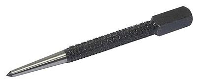
- Appointment of planar marking
- What should be used reinforcing mesh for concrete, wallpaper, plaster technology - plastic, fiberglass or metal
- Edit strip and sheet material
- Open lesson "editing, bending"
- Installation of staircases and platforms: general information
- Repair of pipes of water supply in the apartment Repair of steel pipes
- Markup definition. Planar marking. Types of markup. Questions for self-test