Site sections
Editor's Choice:
- Bathroom faucet device with shower - repair
- If noise interferes with neighbors (memo)
- Why at home may there be a need for measuring water resistance?
- Alteration of "Khrushchev" dvushki almost treshku
- Paint the wallpaper with your own hands
- Installation options for drywall in the bathroom
- Court decision on recovery from the management company of the amount of damage to the gulf of the apartment
- Living room and children in the same room: options for partitions
- Top sofa upholstery rating: customer reviews
- Expansion joints in buildings
Advertising
|
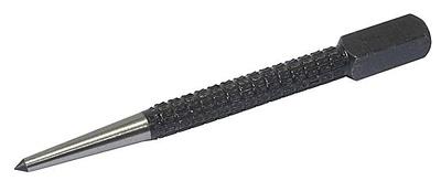
Markup is called drawing on the materials to be processed or on the product being processed points and lines indicating the axes and contours of the part according to the drawing, as well as the places to be processed. The main purpose of the markup is to specify the boundaries to which the workpiece should be processed. The difference between the size of the workpiece before and after processing is called the machining allowance. However, in order to save time, simple blanks are often processed without prior marking (for example, they are sawn to the dimensions shown on the drawing). Sometimes there are two risks: one to indicate the boundary of the treatment, the other at some distance from it - for control. There are planar and spatial markup. Using planar markings, planar parts or individual planes of parts are laid out in case they should not be linked to their other planes. The techniques of planar marking are very similar to those of technical drawing and are carried out with tools like the drawing one. Spatial marking is that the markings of the individual surfaces of the part, located in different planes and at different angles to each other, are linked to each other. For spatial marking, the part is installed on a special marking plate, and the correctness of its installation is carefully checked. When marking, the following tool is used (Fig. 4.2): rulers, packing meter, scriber, punch, steel square, protractor, marking compass, caliper, gauge, etc. Fig. 4.2. Tools used in markup: a - scriber; b - metalwork square; in - marking compasses; g - surface gage; d - caliper. Part marking can be carried out according to the drawing and the template. The markup according to the drawing requires certain skills from the worker: a clear understanding of the drawing or sketch, the correct choice of the base from which the dimensions of the part are deposited, the precise installation of dimensions along the scale bar and their transfer to the part to be marked. Templates are usually used when marking up a large number of flat parts and allow you to significantly simplify and speed up the marking process itself. Patterns are made of sheet steel, aluminum alloys or plywood. To mark the details in this way, the template is placed on the marked sheet, pressed against it and wound around the edges using scriber. It is necessary to keep the scriber at a constant angle to the sheet, not tilting in the direction of the template (or ruler), because this distorts the dimensions of the part. Usually, when drawing scratches, a scriber is kept with a double bias: one at 15-20 ° from the vertical away from the ruler (or template), the other in the direction of movement of the scriber so that the angle between it and the workpiece (part) is 45-70 °. The risk should be carried out only once, and in order to make it as thin as possible, the tip of the scriber must always be well sharpened. So that the lines applied during marking should not be erased during transportation and processing of parts, they are turned through 50-100 mm, and at roundings - through 5-10 mm. The center punch is put on the marked point at first obliquely, and at the moment of impact it is put in a vertical position (Fig. 4.3). The fingers of the holding core should not touch the part to be marked. Blow with the hammer put easily.
Bleeding should be done after all the markup has been completed. It should be remembered that the markup is one of the most crucial operations, ensuring the correct manufacture of the part. Therefore, the worker, making the markup, should be careful, especially when determining the dimensions according to the drawing, applying them to the workpiece, as well as when installing the part on the marking plate. Markup should only be done with a working and accurate tool. Marking is the operation of applying marking lines on the workpiece, defining the contours of the future part or place to be machined. Flat The marking, usually performed on the surface of flat parts, on strip and sheet material, consists in applying to the workpiece contour parallel and perpendicular lines (scratches), circles, arcs, angles, center lines, various geometric shapes according to specified dimensions or contours of different holes using templates . Spatialmarkup is most common in mechanical engineering; and according to methods it is different from the plane. Planar Marking ToolsFor marking use marking plates, linings, swivel devices, jacks, etc. On the marking plate install the parts to be marked and have all the fixtures and tools. The marking plate is cast from fine-grained gray cast iron. The size of the plate is chosen so that its width and length were 500 mm larger than the corresponding dimensions of the marked workpiece. The surface of the slab must always be dry and clean. After work, sweep the slab with a brush, wipe it thoroughly with a cloth, lubricate it with oil to protect it from corrosion and cover it with a wooden shield. Planar marking toolsScriber, vernier caliper, center punch, ruler, square, hammer, etc. Scriber are used for drawing lines (scratches) on the marked surface with a ruler, a square or a template. Scrippers are made of tool steel U10 or U12, sharpened on a cone at an angle of 15-20 0. Kerner -locksmith tools used for applying recesses (cores) on pre-marked lines. The cores are made of tool carbon or alloyed steel U7A, U8A, 7HF or 8HF, at an angle of 50-60 degrees. Compasses used for marking circles and arcs, dividing segments and circles, as well as for geometric constructions. Circles are also used to transfer dimensions from the measuring lines to the part. Reismas is the main tool for spatial marking and is used for drawing parallel, vertical and horizontal lines, as well as for checking the installation of parts on the plate. Preparing for markup.Before marking, you must do the following: Clean the workpiece from dust, dirt, scale, corrosion with a steel brush, etc .; Carefully inspect the workpiece; If shells, bubbles, cracks, etc., are detected, measure them precisely and, drawing up a marking plan, take measures to remove these defects during further processing (if possible); All dimensions of the workpiece must be carefully calculated so that after processing there are no defects on the surface; Examine the drawing of the marking part, find out its features and purpose; Refine dimensions; Determine the base surface of the workpiece, from which you should postpone the dimensions in the process of marking; For planar markings, machined edges of the workpiece or center lines can be used as bases, which are applied first; It is also convenient to take tides, lugs, platics for bases. Marking marks. The marking risks are applied in the following sequence: first, they are horizontal, then vertical, then inclined, and lastly, circles, arcs and curves. Direct risks are caused by a scriber, which must be tilted in the direction of its movement and away from the ruler. Scriber all the time pressed to the ruler, which should fit snugly to the part. Risks spend only once. If the risk is applied poorly, paint over it, allow the dye to dry, and carry out the risk again. Staking lines.The core is called the recess (hole) formed from the action of the tip of the center punch when hit on it with a hammer. Center pins should be located exactly on the marking lines. Marking hammers. For marking work using the hammer number 1 (weighing 200 grams.). Ways of marking.Pattern marking is usually used in the manufacture of large batches of parts of the same shape and size, but sometimes even small batches of complex products are marked up in this way. Pencil markingproduced on a ruler on billets of aluminum and duralumin. It is not allowed to mark the last ones with the help of a scriber, since when applying scratches the protective layer is destroyed and traces of corrosion appear. Defects: The discrepancy between the dimensions of the marked blank and the drawing data due to the inattention of the marker or the inaccuracy of the marking tool Inaccuracy of installation of flightmas on the necessary size; the reason for this is the inattention or inexperience of the razmerchika, the dirty surface of the plate or workpiece; Careless installation of the workpiece on the plate as a result of the alignment of the plate. Safety.Observe the following safety rules: The installation of blanks (parts) on the plate and their removal from the plate must be performed only in mittens; Billets (parts) and fixtures securely install closer to the middle; Before installing the blanks (parts), check the plate for stability; Check the reliability of fastening a hammer on the handle; Remove dust and scale from the marking plate only with a brush, and from large plates - with a broom. In the manufacture of metal products, the starting material - castings, sheet and profile rolled products - does not correspond in size and shape to the designer's drawing. To cut off excess metal, drill, stamp, weld or otherwise process the workpiece, the key points of the drawing are put on it. Applying to these points and lines and processing. The basic concept and types of markupAs a rule, they mark the unique parts and products produced by small and ultra-small series. For large-scale and mass production, the workpieces are not marked, instead, special equipment and control programs are used. What is markupThe operation of applying the dimensions and shape of the product on the workpiece is called marking. The purpose of the operation is to designate the places where the part should be machined and the boundaries of these actions: drilling points, bend lines, weld lines, marking designation, etc.
Risks are scratched into the metal surface with a sharp tool or applied with a marker. Cores are stuffed with a special tool - punch.
According to the method of execution, these types of markup are distinguished:
On the surface of the application are distinguished
The choice between the surface and is determined primarily by the complexity of the spatial configuration of the part. Markup RequirementsPlumbing markup must meet the following requirements:
Part markings should be carried out with high-quality inventory tools and devices subject to periodic calibration. ScratchingThe standard regulates the application of marking lines:
The application of curvilinear elements after rectilinear gives another opportunity to check their accuracy. The arcs should close the straight lines, the conjugation should be smooth. Direct risks are carried out with a well-sharpened scriber, without interruption at one time. At the same time, the scriber is tilted away from the ruler or the square in order not to introduce distortions. Parallel straight lines are drawn using the square and moving it along the baseline to the required distance.
If there are already holes in the workpiece, then a special tool, a center finder, is used to bind marking lines to them. In order to mark the inclined lines, use the marking protractor with a hinged ruler fixed at its zero point. For highly accurate markings in plumbing used calipers. They allow you to measure distances and scratch risks to the nearest hundredths of a millimeter. In order to more accurately carry out risk, cores are put at its beginning and at the end. This allows you to visually control the position of the ruler during drawing.
The lines of the circles are being threaded at four points - the ends of perpendicular diameters. If you mark the already treated surface, the core is used only at the beginning and end of the scratch.
After finishing, the risks are extended to the side surfaces and cores are placed on them. Markup techniquesIn plumbing apply the following techniques:
The selection of techniques is carried out in accordance with the design and technological guidelines. First of all, when marking up a marriage occurs, allowed at the previous stages of manufacture. Products of procurement sites or workshops, as well as materials acquired at other enterprises, find:
Such castings or rolling are not subject to further marking operations, but are returned to the division or organization that allowed the marriage to correct it. At the actual markup stage, a marriage can be caused by the following factors:
Separately, among the reasons for the marriage are the error markers. These include:
Negligence can admit as the mechanic himself, and his leaders, who did not believe in the time tool or issued unsuitable marking devices. Usually marking operations entrust the most experienced and responsible employees, hoping that they will not mechanically transfer dimensions from the drawing to the workpiece, but will treat the matter thoughtfully and timely notice and eliminate the causes of a possible marriage on their own or by contacting their managers. Plumbing markup TO category: Markup Plumbing markup Marking refers to the process of transferring the shape and dimensions of the part or part of it from the drawing to the workpiece. The main purpose of the markup is to designate on the blank the place and boundaries of processing. The machining points are indicated by the centers of the holes obtained by subsequent drilling or bending lines. The boundaries of processing separate the material that must be removed from the material that remains and forms the part. In addition, the markup is used in order to verify the dimensions of the workpiece and its suitability for the manufacture of this part, as well as to control the correctness of the installation of the workpiece on the machine. Workpiece processing can be done without marking, using conductors, stops and other devices. However, the cost of manufacturing such devices pays off only in the production of serial and mass parts. The markup (which is essentially close to technical drawing) is performed, using special tools and devices, on the surfaces of the workpieces. Marking risks, i.e., lines deposited on the surface of the workpiece, indicate the boundaries of processing, and their intersections - the position of the centers of the holes or the position of the centers of the arcs of circles of the mating surfaces. By marking risks produce all subsequent processing of the workpiece. The markup can be mechanized and manual. Mechanized markings performed on coordinate boring machines or other devices that provide accurate movement of the workpiece relative to the marking tool, are used for large, complex and expensive workpieces. Manual marking is performed by toolmakers. Distinguish between surface and spatial markup. Surface markings are performed on one surface of the workpiece, without linking its individual points and lines with points and lines lying on the other surface of this workpiece. The following methods are used: geometric constructions; by pattern or by sample details; using fixtures; on the machine. The most common type of surface marking is planar, used in the manufacture of flat gauges, conductor plates, stamp parts, etc. Spatial marking is performed by linking the dimensions between points and lines lying on different surfaces of the workpiece. The following methods are used: for one installation; with rotation and installation of the workpiece in several positions; combined. Spatial marking is used in the manufacture of parts of complex shape. Tools and devices for marking. According to its purpose, the marking tool is divided into the following types: Scriber used to apply scratches on the surface of the workpiece. Steel scribes are used for marking raw or pre-machined surfaces of the workpieces, brass scriber for marking out brushed and polished surfaces, soft pointed pencils are used for marking accurate and finished surfaces of non-ferrous alloy blanks. Marking compasses on the device and purpose correspond to the drawing and are used for drawing circles and dividing them into parts, transferring linear dimensions, etc.
Fig. 1. Marking tool: a - scriber, b - compass, v - center punch, g - square Steel legs scrolls and compasses are made of steel U7 and Y8 (working ends harden to 52-56 HRC3) and from hard alloys VK.6 and VK8. The working ends of scriber and compasses are sharply sharpened. The thinner and harder the edges of these tools, the thinner the risks are and the more accurate the part will be made. A punch (Fig. 1, c) serves to apply recesses (cores) on the marking risks. This is necessary so that in the course of processing the marking risks, even when erased, are noticeable. Kerner is a steel round core made of alloyed (7HF, 8HF) or carbon (U7A, U8A) steel. Its working part is hardened and sharpened at an angle of 609. The center punch, which is hit with a hammer, is rounded or chamfered and also hardened. Reismas, used in spatial marking for horizontal markings on the marking surface and for checking the position of the workpiece on the marking plate, is made in the form of a stand on which you can move along the height and fix the scriber in the desired position. In the simplest design reismase scriber to the desired height set on a vertical scale ruler or with end measures. In toolmaking, shtangenreismas are mainly used, and sometimes (if necessary) special-designed flights (for example, a multi-pointed flight-plane, having several dashes on a stand, independently set in height to a given size). Combined reysmases are also used, i.e., ordinary reismases equipped additionally with various devices and tools (for example, reismas with a center-finder). The square is used for drawing lines, building corners and checking them. Marking calipers are used to measure the dimensions of the outer and inner surfaces and to carry out marking marks. It differs from conventional calipers by the presence of hard-alloy, sharp-tip tips on its jaws. The devices used for marking and serving for installation, adjustment and fixing of blanks include adjustable wedges, prisms, linings, jacks, cartridges, collets, rectangular magnetic plates, rotary tables, sinus tables, dividing heads and many others. Auxiliary materials are used to prepare the workpiece surfaces for marking. Dust, dirt, rust, scale and oil of the workpiece are cleaned with steel brushes, files, abrasive cloth, wiping tips, napkins, brushes, etc. by layer. Paint should stick well to the surface, dry quickly and remove well. Untreated or coarsely treated surfaces of steel and cast iron blanks are painted with chalk dissolved in water with the addition of wood glue and turpentine (or linseed oil and sikkativa). Pre-treated surfaces are coated with copper sulfate solution. The processed surfaces of the big sizes and aluminum alloys are covered with a special marking varnish. For this purpose, you can use a solution of shellac in alcohol, stained with magenta. Coloring small surfaces is done by cross-brush movements. Large surfaces are spray painted. The painted surface is dried. Sequence of work when marking. The marking includes three stages: preparation of blanks for marking; proper markup and quality control markup. Preparation of the workpiece under the markup is performed as follows: The markup itself is performed in the sequence determined by the markup method. When marking on the template, the latter is installed on the workpiece, correctly oriented it relative to the bases, and secured. The template should fit snugly around the workpiece along the entire contour. Then scroll the outline of the template on the workpiece and detach the template. The markup by the method of geometric constructions is carried out as follows. At first all horizontal are carried out (relative to the base), and then all vertical marking risks; then all rounds, circles are performed and they are joined by straight or inclined lines. When marking, the rack of the reismas is taken by the base and moved along the marking plate relative to the surface of the workpiece, while avoiding a skew. The scrim of reismas touches the vertical surface of the workpiece and leaves it horizontal at risk. Scriber should be at an acute angle to the direction of movement, and the pressure on it should be small and uniform. Risks are held parallel to the working surface of the marking plate. In order for the risks to be strictly linear and horizontal, the support surfaces of the reismas and the marking plate must be processed with great precision. The markup quality is improved if a flat scriber is used in the flightmaker. Quality control of marking and core is the final stage of marking. Core centers should be located exactly on the marking risks, cores should not be too deep and differ from each other in size. On direct risks, cores are punched at distances of 10-20 mm, on curvilinear ones - 5-10 mm. The distances between the cores perform the same. With an increase in the size of the workpiece, the distance between the cores also increases. The points of conjugation and the intersection of marking marks are necessarily kern. The marking risks on the processed surfaces of precision products are not kern. Marriage in the markup can lead to significant material losses. Its most frequent causes are: wrong choice of bases and their poor preparation; errors when reading a drawing, when postponing dimensions and in calculations; wrong choice of marking tools, devices, their malfunction; wrong methods and methods of markup. The widespread use of mechanized marking tools and devices improves the quality and performance of the markup. Therefore, mechanical, electrical and pneumatic cores, calipers and calipers with electronic indication, mechanized devices for installation, alignment and fixing of blanks should be widely used. Significantly speeds up the work and reduces the number of errors the application for the calculation of calculators. It should create more versatile and easy-to-use marking tools and fixtures. Where it is economically justified, use coordinate machines, coordinate measuring machines for marking, or eliminate marking altogether by machining blanks on CNC machines. Markupcall the process of transferring the shape and dimensions of the part or part thereof from the drawing to the workpiece, in order to mark on the workpiece the place and boundaries of processing. The boundaries of processing separate the material that must be removed from the material that remains and forms the part. The markup is performed using various tools, which are divided into the following types: (Fig.1.2) 1) for making scratches and applying dimples (scriber, compasses, center pins); 2) to measure and control linear and angular values (metal rulers, calipers, squares, micrometers, protractors, etc.); 3) combined, allowing to make measurements and carry out risks (marking calipers, gauge races, etc.). Scriberused for applying scratches on the surface of the workpieces. Marking compassesaccording to their design and purpose, they correspond to the drawing ones and serve to draw circles, transfer linear dimensions. The steel legs of scriber and compasses are made of steel U7 and Y8, the working ends of scriber and compasses are sharpened. Punchserves for drawing dimples on the marking risks, so that in the course of processing the marking risks, even when erased, are noticeable. The core is a steel round core, made of alloyed (7HF, 8HF) or carbon steel (V7A, V8A) steel. His working part is hardened and sharpened at an angle of 60 o. Squaresused for drawing lines, angles and checking them . Marking Caliperit is used to measure the dimensions of external and internal surfaces and to carry out marking marks. It differs from ordinary calipers by the presence of sharply sharpened carbide tips on its carbide jaws. Felling Cutting -method of metalwork processing of workpieces with the help of a chisel or crossbutton. The cutting removes excess metal, chops up the burrs on the parts, cuts down the shells, non-metallic inclusions, lubricating and keyways, smooths the welds. Cutting is done in cases where special precision is not required and a small metal layer must be removed from the part. This work is laborious and inefficient, demanding a lot of physical force, is performed using a chisel, cross bar and a hammer, used only in cases where it is impossible to use machining. In the process of cutting, the cutting tool is held with the left hand at the middle part, and the hammer is held at the right and is hit with a hammer with such force that the chisel blade hits the metal. To increase the productivity (6-8 times) of the cutting process, pneumatic and electric chipping hammers are used. Due to air pressure R = 5-6 atm and the electromagnetic field is provided by the reciprocating motion of the striker. Chisels(GOST 7211-94) are used for cutting of metals and are produced in length and width respectively 100 (5), 125 (10), 150 (15), 175 (20) and 200 (25) mm. The angle of the tip is chosen: for a solid metal 70 o, for an average - 60 o and for a soft one - 45 o. (fig. 1.4) Creutzmeisel -it is used for cutting out narrow grooves and keyways and differs from a chisel in a narrower cutting part. Angles of sharpening and training are similar to a chisel. Chisels and crossheads are made from alloyed (7HF and 8HF) or carbon (U7A and U8A) steel. |


New
- Installation of a faltsevy roof the hands: the step-by-step instruction
- Features plastering tetrahedral columns with a dry mixture
- How to rivet a rivet - automatic and manual methods for different materials What rivet rivet steel sheets
- Appointment of planar marking
- What should be used reinforcing mesh for concrete, wallpaper, plaster technology - plastic, fiberglass or metal
- Edit strip and sheet material
- Open lesson "editing, bending"
- Installation of staircases and platforms: general information
- Repair of pipes of water supply in the apartment Repair of steel pipes
- Markup definition. Planar marking. Types of markup. Questions for self-test